Hwayi
(i) volume classification to double rotation the rationale is to use the re-entry effect of the piston in the cylinder to change the contents of the cylinder repeatedly so that the work volume between the rotor and the shell is changed by the rotation of the rotor or rotor parts in the shell for the purpose of inhaling and ejecting the fluid animation presentation
Pistol pump gear pump, screw pump (ii) blade
The main structures of the blade pumps and wind machines are rotaryable, leafy wheels and fixed shells. The fluids are given energy by rotating the wheel. Depending on the flow of fluids, they can be further divided into the following types: the centrifugal force generated by the high-speed rotation of the centrifugal axial hybrid flow fundamentals of the locomotives allows the fluids to gain energy from the extruded propulsion of the energy rotor blades, and the fluids to gain energy by increasing their pressure and kinetic centrifugal and axial hybrids to demonstrate the overall structure of the functional components and the overall structure of the functional components to do the overall structure of the functional components
See section ii (abbreviated) of the latter section for examples of cac products mixed with axle-flow pump from the centrifuge central air conditioner or cold bank for the domestic air-conditioning indoor wind machine
I. Rationale for centrifuge pumps and wind machines
The centrifugal power generated by the high-speed rotation of the working principle leaves gives the fluid energy, i. E., when it passes through the wheel, both the pressure and the kinetic energy are enhanced and can be transported to a high or distant location. When the wheel is rotated, the fluid axis flows in, then 90 degrees into and out of the rotation channel. The wheel rotates continuously, creating a vacuum at the entrance to the wheel, thus allowing the fluid to be pumped and discharged continuously. Figure performance
Overall structure
Ii. Axis-stream pumps and wind engine working principles
The working method of the axle stream pumps and wind machines is that the wind engine structure is shown in the following two charts to the left, and the third figure is the structure of the axle current pumps (see figure)
I don't know. The squeezing propulsion of the rotating blades gives the fluid energy, increasing its pressure and kinetic energy, and the wheel is installed in a drum (winder cone) pump shell. When the wheel is rotated, the fluid axis flows in and out of the axis after the energy is obtained within the leaf channel. Axle current pumps and wind machines are used for high flow, low pressure and are often used in refrigeration systems as circular pumps and wind transmitters. Figure performance
Iii. The working principles of the flow wind machine
The development of air-regulating technologies requires a small wind machine with a small wind volume, low noise, proper head pressure and installed to accommodate the building. Transcontinental windmills are the new type of wind machine that adapts to this requirement. Figure performance
The main features of trans-stream windmills in recent years are as follows: (i) the wheel is generally multi-leaved, but both ends are closed. (ii) the width of the wheelb is not limited and when the width increases ... The flow increases. (iii) transcontinental wind machines, unlike centrifuges, open the wind-flow axis on the side plate of the shell to enter the phoenix machine, and partially open the shell to allow the flow directly into the wind machine. The air flows through the leaves twice. Certain transcontinental wind turbines are equipped with non-discretionary directional blades on the inner edge of the wheel to improve the air flow. (iv) in performance, the flow wind machine has a high overall pressure factor. The performance curve is bee-typed and less efficient, usually about 30% to 50%. (v) both the vent and the vent are rectangular and easily fit with the building. Many issues remain to be resolved. In particular, the geometric shape of the components has a significant impact on their performance. Inadequate structures are not even working at all, but the use of small transient wind machines is steadily expanding. Iv. Other commonly used pumps
1. The working method of the pump is to drive the piston movement using the rotation of the eccentric axis through a collage device to convert the rounding of the axis to the piston's retroactivity. Pistols continue to move back and forth, and the pumping of water between the pump and the pressure is continuously alternating. Figure performance
Overall structure sp&nspspspsp&nspsp sp&nb b&nb&nspb&nspp&nsppsp psp&nb&nb b&nb&nspb&nspb&nb p&nb&nspb&nspb&nspb&nb b&nspb&nspb&nb&nspb&nspb&nsp
Water ring vacuum pumps
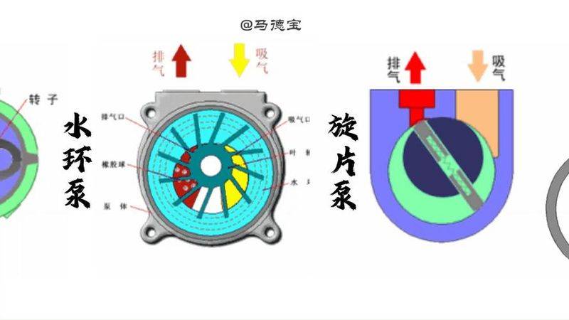
The working principle is that the blades of the water-cycle vacuum pump are eccentricly packed in the cylindrical pump shell. A certain amount of water is injected into the pump. When the wheel rotates, the water is thrown into the pump shell to form a water ring with the inner surface of the ring that corresponds to the rim. Due to the fact that the pump casings are different from the leaf wheels, the inflow space between the right half-wheel rim and the water ring is gradually expanding, creating a vacuum that allows the gas to enter the pump interior. The gas then enters the left half, increasing the pressure by gradually compressing the volume between the rings, and the gas is discharged out of the pump through the vent space and the exhaust pipe. Figure performance
3. The working principles of rotz vacuum pumps
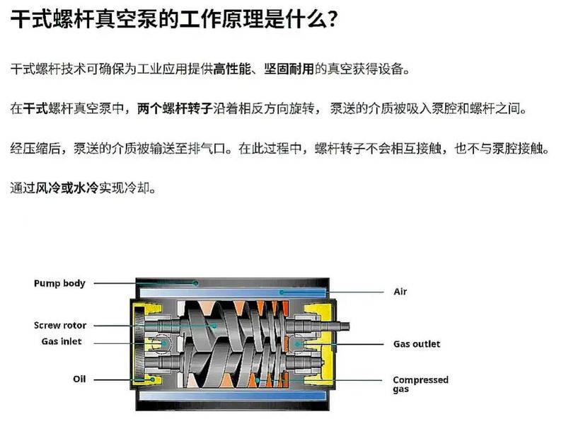
The working principles of the roz pump are similar to those of the roz blower. Due to the constant rotation of the rotor, the gas is pumped from the vent to the space of v0 between the rotor and the pump shell, which is then discharged through the vent. The gas in the pump cavity was not compressed or swelled, as the v0 space was completely closed after inhalation. However, when the top of the rotor turns to the edge of the vent, the v0 space connects with the side of the vent, because of the higher pressure of the gas on the side of the vent, a portion of the gas is repulsed into space v0, which suddenly increases the pressure of the gas. When the rotor continues to rotate, the gas is discharged from the pump. In general, the rotz pump has the following characteristics: as a result, rotz pumps are widely used in the metallurgy, petrochemical, paper, food and electronics industries. Figure performance
4. Principles for working on a spiral vacuum pump
The working principle is a voltaic vacuum pump (referred to as a propeller pump) as an oil-covered mechanical vacuum pump. The working pressure range of 101325 ~ 1. 33 x 10-2 (pa) is low vacuum pump. It can be used alone or as a front-stage pump for other high or super-high vacuum pumps. It has been widely applied in the production and research sectors of metallurgy, machinery, military engineering, electronics, chemicals, light engineering, oil and medicine. The pump consists mainly of pumps, rotors, rotors, caps, springs, etc. A rotor is eccentricly installed in the internal cavity of the rotor pump, and the rotor outer circle corresponds to the internal surface of the pump cavity (with a small gap between the two) and the rotor slot contains two spins with springs. When rotated, the pressure of centrifugal force and spring kept the top of the blade in contact with the inner wall of the pump cavity, and the rotor rotated the blade slid along the inner wall of the pump cavity. The two blades divide the lunar tooth space surrounding the rotor, pump cavity and the two end caps into parts a, b and c. When the rotor rotates in the direction of the arrow, the volume of space a, which connects to the inhaler, is gradually increasing and is inhaling. The volume of space c, which is connected to the vent, is gradually shrinking and is in the process of exhausting. The volume of the middle space b is also gradually decreasing and is being compressed. As the volume of space a is gradually increasing (i. E. Expansion), the pressure of the gas is reduced and the external pressure of the gas at the entrance to the pump is stronger than the pressure in space a, thus inhaling the gas. When space a is isolated from the inhaler, i. E., transferred to the position of space b, the gas begins to be compressed, the volume is gradually reduced and finally connected to the vent. When the compressed gas exceeds the pressure of the exhaust pressure, the exhaust valve is pushed away by the compressed gas, which runs through the oil layer inside the tank into the atmosphere. Pumps are running continuously for the purpose of continuous pumping. A two-stage pump is formed if the discharged gas is transferred to another stage (low vacuum level) via the gas channel, removed from the low vacuum level and then recalculated by the low vacuum level into the atmosphere. The overall compression ratio is then burdened by two levels, thus increasing the limit vacuum. Figure performance
5. The working principle of the gear pump is that the gear pump has a pair of gears that are coiled with each other, as shown in the chart, the active wheel of the gear is attached to the active axis, the outer shell of one end of the axis is driven by the original motive, and the other gear is loaded from the wheel to the other, and, when the gear rotates, the liquid enters into the inhaling space along the suction tube, and is squeezed along the upper and lower shell walls by two gears, respectively, to the discharge space (in front of the teeth and rods), and then into the pressure pipe. Figure performance
Vii. Pumping principles
The working principle screw pump is a rotary pump that uses the screws to collide with each other to inhal and discharge liquids. The rotor of the screw pump consists of a active screw (which may be either one or two or three) and a moving screw. Proactive screws rotate in the opposite direction from the kinetic screws, the threads collide with each other, the fluid enters from the inhaler and is pushed forward by the spiral to the discharge. This pump applies to high pressure, small flow. Refrigeration systems are often used as oil pumps for the transmission of axle lubricating oils and speeders. Figure performance
8. The operation of jet pumps
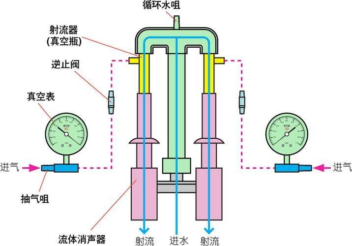
The principle of operation is to move liquids (or gases) outside the nozzle from high pressure work fluids 7 to work nozzles 6 from the pressure pipe, which can be converted to high-speed kinetic energy by the nozzle pressure. At this point, the high speed of the nozzle exit creates a vacuum in the larynx in chamber 2, so that suction fluid 8 enters continuously with the working fluid 7 and then transmits the pressure slightly higher through the proliferation chamber. Work fluids continue to eject vacuums in the inhaling room, thus allowing continuous suction and discharge. Work fluids may be high-voltage vapours or high-voltage water, the former referred to as vapour pumps and the latter as water pumpers. Such pumps are less common in refrigeration systems. Figure performance