1 lte system standard evolution
With the emergence of broadband wireless access, the business demand for mobile and broadbanded access has increased, as has the demand of users for mobile communication networks, and it can be seen that high-speed broadband access is a basic requirement for future mobile communication systems. The imt-advanced system needs to be clear: the future mobile communication system can support the peak speed rate of 100 mbit/s in a high-speed movement scenario and the peak rate of 1 gbit/s in a low-speed move scenario。
Lte (long term evolution) is a 3gp long-term evolution project, compatible with the current 3g communication system and evolving 3g. It has high transmission rates, high transmission quality and high mobility, improving and enhancing 3g air access technology, using ofdm and mimo technology as its only standard for wireless network evolution. A peak rate of 100 mbit/s in the lower row and 50 mbit/s in the upper row can be provided at 20 mhz spectrum bandwidth。
Since the launch of the lte project in november 2004, the lte research has been vigorously pursued by the 3gp with frequent meetings and needs development has been completed in only six months. In june 2006, the tsg of the 3gpp ran (wireless access network) started the lte phase, but after difficult discussions and integration, most of the basic technical framework was finally defined, and an initial lte system was gradually presented to us。
The lte system starts with defined needs. Key needs indicators include:
Support 1. 4~20 mhz bandwidth。
Peak data rate: 50 mbit/s in line, 100 mbit/s in line. Spectrum efficiency is 2-4 times greater than 3gp r6。
Increase the bit rate at the edge of the district。
User-face delay (one-way)
Supporting interoperability with existing 3gpp and non-3gp systems。
Support for enhanced multi-broadcast operations。
Reduce the cost of networking and achieve a low-cost evolution from r6。
Achieving reasonable terminal complexity, cost and power consumption。
Support enhanced ims (ip multimedia subsystem) and core network。
Backward compatibility should be pursued, but the balance between improved performance and backward compatibility should be carefully considered。
The cs (wire exchange) domain is cancelled and cs-based operations are performed in ps (package exchange) domain, such as the use of voip。
Optimizing low-speed mobility while supporting high-speed mobility。
A pair of pairs (paired) and a pair of unpaired bands are supported with as similar technology as possible。
Support as much as possible simple ad hoc coexistence。
In response to the location of wimax's “low-mobility broadband ip access”, the lte system identified corresponding needs, such as similar bandwidth, data rates and spectrum efficiency indicators, the optimization of low mobility, the support of only ps domains, and the emphasis on broadcast multiple broadcasting operations. At the same time, due to the importance attached to voip and online games, lte's demand for user-level delays is almost stringent. The requirement for backward compatibility seems ambiguous, and the selection of a large number of new technologies has made it difficult to maintain a smooth transition from the 3g system in the physical layer. The lte system, like wimax, chose ofdm as the basic technology, not the cdma technology。
As mentioned earlier, the lte system imposes stricter requirements for the duration of the system:
Significant reduction of control surface time: 100 ms: lte idle→lte active; 50 ms: dormant→active 50ms。
User-face time extension: is defined as the time of transfer of the ip layer data from the ue or ran edge node to the ran edge node or the ue ip package data。
Demand: 5 ms (subsequent additional definition is required in the absence of a loaded ip package)。
In order to meet the above requirements, in addition to changes in the length of the wireless frame of the air interface and changes such as tti to reduce delays in the air interface, there is a need to evolve the network structure to minimize excess nodes, thereby reducing transmission time delays in the network. However, regardless of the evolution of the structure, wireless and core networks continue to follow the principles of their development, and air interfaces are terminated in wireless networks. As a result, the logical relationship between wireless access and the core network still exists and the interface between wireless access and the core network remains clear。
Based on the above background, the lte system has, at the basic technical stage, selected technologies such as ofdm, mimo and smart antennas as basic physical layer technologies and retained both the fdd and tdd-type lte technologies. Some of the commonalities and differences between the two patterns are further analysed below。
2 fdd equals tdd spectrum efficiency under the same conditions
The differences between the basic frame structure of the lte fdd and the lte tdd system (i. E. Td-lte) are not analysed here. In terms of basic frame structure, the tdd system retains three special time slots from the design of the td-scdma system and, in order to accommodate the integration of the wireless frame, has designed different top/down time gap ratios and different symbol ratios for the special time gap. As far as spectrum efficiency is concerned, the results of our simulation show that the two are essentially equal。
Simulation condition:
Network model: 19x3。
Frequency band and carrier bandwidth 2ghz, bw 20mhz。
Communication environment: urban macro。
Chain model: scm-e, 3km/h。
Base station launch power: pbs max:46dbm。
Tdd configuration: tdd ul: dl, 2:2; special fRame: 10:2:2。
Terminal launch power: pue max:23bm。
Terminal height: 1. 5 m。
Next: scheme: rrank1/rank2 self-adaptation; no power control。
Upline: scheme: irc (disturbing a concerted merger), upline power is open。
Based on the same conditions described above, the results are modelled as shown in table 1。
Table 1 simulation results
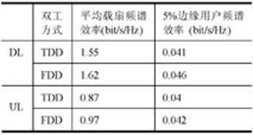
A comparison of table 1 shows that both the uplink and downlinks, the tdd system and the fdd system are basically equivalent to spectrum efficiency, with the average frequency spectrum efficiency of the downlink being dl: 1. 5 ~1. 6 (bit/s/hz), while the result of the uplink is only 0. 1 bit/s/hz. The marginal user spectrum efficiency of the two systems is virtually non-differentiated, meaning that the marginal user experience of the two systems is fully consistent。
By imitating true comparisons, it can be seen that the tdd system is comparable to the spectrum efficiency of the fdd system. What are the differences between the tdd and the fdd systems
3 tdd system supports 8t8r beamforming
The use of smart antenna technology in the td-scdma system marked a breakthrough in the multi antenna technology of the tdd system. The lte tdd system considered support for multi antenna technology at the early stages of its design, and the lte system, although not a cdma system, is equally capable of using multi antenna technology (see figure 1)。
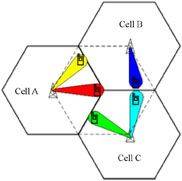
Figure 1 multi antenna technology
The distinguishing sign of multi- antenna technology is the beamforming, which points the main signal to the target terminal through the dynamic beaming. For this purpose, the base station must be able to obtain an accurate estimate of the channel and use csi information to calculate the weight to send the signal. This feature is achieved mainly by using the same frequency points in the up/downlinks of the tdd system, so that the base station can predict the conditions of the lower channel by using the judgement (phases and power or belief noise ratios of different antennas) to receive the signal from the upper channel, thus enabling the beam to be shaped. No additional funds are needed to estimate the cost of the channel, and real time is better. For the fdd system, because the upper/downlink is launched using different frequency points, if the base station wishes to be be beamed to the ue, then the ue is required to estimate the lower channel and quickly provide feedback to the base station, the channel changes rapidly in a high-speed moving environment, the estimated cost of the message will be high, and due to the delay in the feedback of the ue, the real-time nature of the believed estimate cannot be guaranteed, and the intelligent antenna is largely unworkable。
In summary, smart antenna technology is more suitable for the td-lte system, which is unique to the tdd system (see figure 2)。
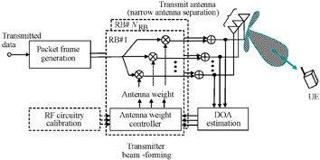
Figure 2 application of smart antenna technology in the td-lte system
4 8t8r to 2t2r under same frequency bands
Given the relative efficiency of the spectrum and the unique multi- antenna advantage of the tdd system, let's look at the performance of the tdd system in terms of throughput rates and coverage with the fdd system (conventional 2 antennas) under eight antenna conditions。
Similarly, we compare the results with the results of the simulation (see figure 3), under the following conditions:
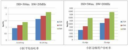
Figure 3 comparison of simulation results
Marginality rate required ul: 307 kbit/s, dl: 1024 kbit/s。
Frequency 1. 8 ghz, system bandwidth 20 mhz, and frequency network 1x3x1。
Cpe terminal: pue max: 26dbm, height 5m/25m; terminal antenna gain 2dbi。
In densely populated urban areas, the outer base is 45 m。
Antenna gain of 18dbi-2t; 17dbi-4t; 15dbi-8t。
Base station launch power: pbs max:46dbm。
Dissemination model cost231-hata classic。
Td-lte uses the 8t8r beamforming advanced switch; the 1x8 irc technology is used in the upper row。
2t2r mimo advanced witch; 1x2 irc technology for upper rows。
A comparison of the simulation results in figure 3 shows clearly that, under the same band, td-lte 8t8r will yield significant gains in the average throughput rate and marginal throughput rate in the subsector compared to fdd lte 2t2r:
The average gain in throughput rate was about 50 per cent in the upper sector; the gain in throughput rate was more than 100 per cent in the marginal group。
Average throughput gains of about 25 per cent in the lower sector and 70 per cent in the marginal region。
What about the results of the comparison between the two in terms of coverage capacity? The results of figure 4 can be seen further。
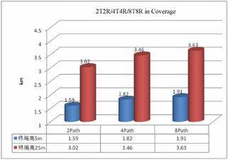
Figure 4 results of the comparison between the two in terms of coverage capacity
By the same token, in terms of coverage, we can get results as shown in table 2 through a simulation comparison。
Table 2
This simulation leads to the conclusion that the tdd system of 8t8r has a clear advantage over the fdd system of 2t2r, both in terms of throughput rates and coverage capabilities。
5 tdd also supports multi-user beamforming
The tdd system can also support multi-user beam beaming by using smart antenna technology. The rationale is that, in order to increase the capacity of the system, the lte tdd system allocates multiple data streams through the beamforming mode to multiple and diverse users with the same time-frequency resources to improve spectrum utilization (see figure 5)。
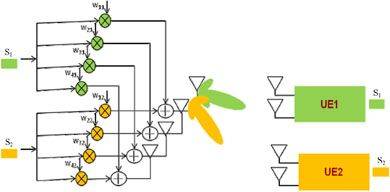
Figure 5 tdd support multi-user beamforming
Multi-user beamforming can be achieved as long as two combinations are less relevant to the user's channel。
The adoption of multi-user beamforming will result in a significant increase in regional throughput rates relative to the single-data stream beamforming transmission mode。
6 concluding remarks
Multiple antenna technology is one of the mainstream technologies that operators wish to apply overseas with the application of the td-scdma system and with the application of wimax。
China has accumulated a wealth of sufficient multi- antenna networks and performance experience for the deployment of a global current network of technology research and development and product solutions in the area of multi- antenna technology over many years. In the domestic td-lte technical experiment, which began in 2009, and in the ministry of industry and communications's td-lte scale technical test in 2011, the eight antenna-related infield tests in china showed excellent indicators, leading to the validation of a large-scale network of physical exterior sites。
This paper describes the unique advantages of using the 8-channel antenna in the td-lte system by comparing it with the 2t2r lte fdd system on spectrum efficiency, throughput rates, and overlay capabilities. It is believed that, as multi- antenna technology and further optimization, as well as further evolution and upgrading in the shape of antenna product specifications, multi- antenna technology will inevitably bring added value to the deployment and operation of the lte system, such as reduced costs and reduced engineering volume and difficulty, and become the preferred technology for operators。