
This practical novelty relates to the technical area of the heat-replacement unit and, more specifically, to a recycle-pump dust shield for the heat-replacement station。
Background technology:
The recycle pumps in the heat exchanger unit are exposed to the operation of the unit for long periods of time, because of the complexity of the site environment in which they operate, which makes them vulnerable to large quantities of dust or sewage erosion, leading to a shorter life of the recycle pump, while the water pump signs are perishable and do not facilitate maintenance and replacement; the presence of a dust shield on the cycle pump will effectively address the above-mentioned problems, but the general dust shield, which, through its support pole, is installed on the base of the unit, takes up a larger space, is not easily disassembled, and, owing to the different types of the recycle pump, requires a specific dust shield for each cycle pump, which does not apply to batch quantification, increases production costs, affects the dispersive and normal operation of the recycle pump, and the existing dust shield can easily lead to the dissipation of the recycle pump, so that it is necessary to design a reheating station with a recycle pump。
Technical realization elements:
This practical novel is intended to address the issues raised in the above-mentioned context and thus provide a reheating station-cycle pump dust shield。
For the above purposes, this practical novel offers the following technical options: a recycle pump protection shield for a heat exchange station, including the installation of a floor, pole, lift and drop ring, tight bolts, welding poles, shielding body and observation window, a welding pole on the upper left side of the upper surface of the installed plate, a lift and dropring ring on the upper end of the frame, a tight bolt to the left thread of the lifting and drop rings, a welding bar on the right side of the lift and dropring ring, a shielding pad on the right side of the said welding pole, an observation window on the central placement on the upper surface of the said shield, and an air-lifting device on the bottom of the said shield
(a) the shield element in question consists of a rectangular frame, top block, slide and first block, the lower welding of the shield in question has a rectangular frame, the top welding of the outer wall of the rectangular frame in question has a top frame, the center of the outer wall on both sides of the rectangular frame in question has a slide and the lower side of the slide in question has a first block
The aerometric lift-down devices in question include a rectangle frame, rectangular veil, slide slot and second block, a rectangular veil at the top of the inner wall of the ascending-down rectangular frame in question, a slide slot at the centre of the inner wall on both sides of the ascending-down rectangular frame in question, and a second block at the top of the slider in question。
On top of this, the four corners of the said installation plate are covered by bolt holes。
On the preferred side, the said lift-down loop can move and rotate up and down the pole, and the tight bolts are attached to the pole on the side of the lift-down loop。
If you prefer, the slide of the ascending/falling rectangular frame is attached to the rectangular frame。
Optimal, the slider and first block are embedded in the slider。
On the preferred side, the thickness of the first and second blocks is the same and the thickness of the first and second blocks is one half of the depth of the slider slot。
If you prefer, the upper surface of the rectangular veil in question is sewn by a needle。
On the preferred basis, the observation window in question is transparent steeled glass。
A recycle pump dust shield for a heat exchange station provided by this practical novel has the following beneficial effects:
1. The circulatory pump shield is equipped with an up and down ring, which is rotated along the vertical pole by removing a tight bolt from the floor installed next to the cycle pump, leaving the shield and air lifts at the top of the cycle pump, and then moving down so that the shield and air lifts are covered by the cycle pump to facilitate dismantling and protection。
2. The circulatory pump is equipped with an air lift and drop-off device, which allows the slide on the shield body to move along the slide on the rectangular frame and thus to apply to different sizes of the cycle pump by placing a slider on the air lift ore。
3. The circulatory gas from the circulatory-pump shield is fitted with a rectangular veil with a rectangular veil and a top-barrel frame, which prevents dust from falling into the rectangular web, and a sew on the rectangular web, which effectively prevents dust from entering from the rectangular veil to the air-lifting device, and allows thermal gas from the circulation pump to be discharged through the rectangular web。
4. The circulatory pump dust shield is equipped with an observation window, which allows not only protection but also easy observation of the type of the circulatory pump by setting the observation window into transparent steeled glass。
Annex figure description
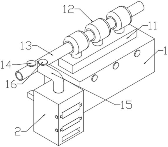
Figure 1 illustrates the current practical and new structure。
Figure 2 provides a map of this practical and new installation floor structure。
Figure 3 provides a graph of this practical and new protection matrix structure。
Figure 4 illustrates the structure of this practical and new type of air-lifting devices。
Figure 5 shows the magnification structure in figure 4 in this practical and new form。
Figure 1-5 shows: 1 - installation of bottom plates, 101 - bolt holes, 2 - vertical poles, 3 - up and down loops, 4 - hard bolts, 5 - welding poles, 6 - shielding body, 601 - rectangular frames, 602 - upper frame, 603 - slide track, 604 - first block, 7 - observation window, 8 - air-lifters, 801 - litre rectangular frames, 802 - rectangles, 803 - slides, 804 - second block。
Implementation modalities
The following is a clear and complete description of the technical options in this new practical implementation, taking into account the attached chart of the new practical implementation, which is clearly a partial rather than a complete one. On the basis of the implementation of this new practical approach, all other examples of implementation obtained by ordinary technicians in this field without creative work fall within the scope of the new practical protection。
See figure 1 to 5, for a practical new implementation example, for a recycle pump protection shield for a heat exchange station, including a bottom plate 1, a vertical pole 2, a lift-down ring 3, a tight bolt 4, a welder 5, a shield body 6 and an observation window 7, a top-left welding line 2 to the top surface of panel 1, a lift-down ring 3 to the top of the pole 2, a fixed bolt 4 to the left thread of a lift-down ring 3, a welding bar 5 to the right of a lift-down ring 3 and a protection shield 5 to the right welding line 5 to the right of a welder. (b) body 6, central embedding setting of the upper surface of the shield element 6 with observation window 7 and air-lifting device 8 at the bottom of the shield element 6
The shield element 6 includes rectangular 601, top 602, slide 603 and first block 604, shield the lower welding of this body 6 has rectangular box 601, the top welding of the outer wall of rectangular 601, the center of both sides of the outer wall of rectangular 601 has a slide 603 and the outer side of the slide 603 has a first block 604
Anticipator 8 includes a rectangular box 801, a rectangular net 802, a slide slot 803 and a second block 804, a rectangular net 802 welded at the top of the inner wall of rectangular box 801, a slide slot 803 at the center of the inner wall of the back and back of the rectangular box 801, and a second block 804 at the top of the slider slot 803。
In this implementation example, the four corners of panel 1 are running through the opening of bolt holes 101 to facilitate the installation of panel 1。
In this example, the lift-down loop 3 moves and rotates up and down two poles, and the tight bolt 4 runs right through the side of the lift-down trap 3 to the length of two poles, making the slide-proof shield body6 and air-lifting devices8 can rotate up and down 360° along the vertical pole, making it easier to protect。
In this implementation example, the rectangular 801 slider suite is attached to rectangular 601 and can be moved down to the shield core 6, depending on the size of the cycle pump, so that the inner space of the shield core 6 is suitable for the size of the cycle pump。
In this implementation example, the slide track 603 and block 604 are embedded in the slide slot 803, allowing for a 6-litre decomposition of the protective shield。
In this implementation example, the thickness of block 604 and block 804 is the same as that of block 804, and the thickness of block 604 and block 804 is one half of the depth of the slider 803 and the first block 604 and block 804 are combined so that the air lift-down device8 does not fall off the shield core 6。
In this implementation example, the upper surface of the rectangular veil of 802 is sewn through a needle line and has rectangles that effectively contain dust。
In this example, observation window 7 is a transparent steel-coated glass material that allows for observation while protecting。
Of these, it is noted that the adjustments to lift-down loop 3, shield-matrix6 and air-lifting unit8 are manually operated by staff。
When using this practical new type of heat exchange station recycle pump shield, first the device will be installed and, if necessary, the shield will be moved down to the top of the recycle pump by installing the bottom plate 1 next to the recycle pump, and by lifting the tight bolt 4 so that the leash 4 rotates along the vertical pole 3 so that the shield core 6 and the air lift device 8 are placed on the top of the recycle pump, and then moving down to the ring 3 so that the shield the body 6 and the gas lift-down device 8 are covered in the cycle pump, allowing for easy disassembly and protection, moving downwards up and down rings 4 depending on the size of the cycle pump, moving the shield hull 6 downwards, allowing the slide of 603 on the shield hull 6 to drop down along the slide slot 803 on the lift-down rectangular box 8 and allowing the interior space of the shield hull 6 to be applied to the size of the cycle pump, thermal gas generated by the circulation pump to be discharged through a rectangular veil of 802 and the sew on the rectangular hull of 802 to allow an effective block of dust from the rectangular veil 802 into the air-lifting unit 8 and to be observed through window 7。
It should be noted that for technical staff in this field, a number of variations and improvements can be made, which should also be considered as the scope of protection of the practical new concept, without prejudice to the effectiveness of the practical new application and the usefulness of patents。


