Seismic wave detection techniques are defined as the geological structure of the front of the inverse project (e. G., in front of the hands of the tunnel) by detecting, analysing or analysing the reflection, refraction or rectangular signals of seismic waves, using differences in characteristics (e. G., speed, amplitude, frequency, etc.) when seismic waves are transmitted in different geological media, so as to identify, in advance, adverse geological bodies such as geological layers, faults, dissolved holes, shredding bands, rich water formations, etc。
I. Rationale for seismic wave detection techniques
It can be divided into the following key elements:
1. Seismic wave stimulation: artificial seismic sources generate detection signals
In supra-precedent geological forecasts, seismometers need to rely on artificially activated seismic waves as “detection signals”. The energy released by the earthquake usually generates two major seismic waves at a certain distance from the construction surface (e. G., the tunnel side wall) (e. G., explosives, hammers, air guns, etc.):
(a) twisted wave (p wave): the mass-point vibration direction is consistent with the wave's transmission direction, which can be transmitted in solids, liquids, gases, and faster (usually 2-6 km/s in rock)
Transverse wave (s wave): the mass-point vibration direction is vertically related to the wave's transmission direction, can be transmitted only in solids, at a slower rate (about 0. 5-0. 6 times the p wave) and is more sensitive to faults and fluids in the medium。
These seismic waves can spread into the underground medium in front of the palm, becoming a “carrier” for detecting underground structures。
2. Seismic wave transmission and reflection: signal changes in the geological interface
Seismic waves are transmitted along straight lines in the flat media, but when encountered with interfaces of different geological bodies (e. G. Rocky mutations, fault breaks, dissolved boundary, rich water layer, etc.), seismic waves reflect, reflect or recoil due to differences in density and elasticity modulations between the interfaces:
(a) reflection wave: part of the energy returns in the reverse direction of the original transmission path and is captured by the seismometer receiver
Refraction / circular wave: part of the energy changes the direction of the transmission and continues to spread through the interface, whose signal characteristics can also be used to analyse the nature of the interface。
The interface of adverse geological bodies (e. G. Faults, dissolved holes) usually produces stronger reflective signals, and parameters such as the time, amplitude, frequency, etc. Of the reflection wave can differ significantly from the communication properties in normal rock bodies。
Signal reception and recording: seismometer capture of reflection wave information
After the earthquake is triggered, the seismometer receives a reflection signal through a wave detector (receiver) pre-positioned near the construction surface (e. G., the tunnel side wall, behind the palm). The sensor converts ground vibrations caused by seismic waves into telecommunications numbers, which are recorded by the seismometer mainframe, to generate raw seismic data containing information on time, amplitude, frequency, etc。
In order to improve the accuracy of the signal, multiple detectors (forming “observation arrays”) are usually installed and interference (e. G., construction vibrations, environmental noise) is eliminated by means of multiple triggers。
4. Data processing and inversion: deconstructing underground geological structures
The original seismic data need to be professionally processed (e. G., filtering, correction, supercharge, offset imaging, etc.) to eliminate interference signals and reverse the geological situation ahead by the following key parameters:
Travel time: the reflection wave from the source of the earthquake to the interface before returning to the time of transmission of the detector can be calculated at the distance between the reflection interface and the observation point (formula: distance = wave speed x travel time / 2, to be divided by 2 due to round-trip transmission) in combination with the known seismic wave speed (which can be obtained through pre-test or empirical values)
Wave speed differences: p- and s-waves vary in different geological bodies (e. G. Break zone wave speeds are below full rock, air/water wave speeds are much below rock) and the medium properties can be judged by analysing wave speed changes
Amplitudes and frequencies: responsive wave amplitudes in adverse geological interfaces are usually stronger (due to large variations in media) and may be lower (due to rapid energy decay) and assist in identifying faults, dissolved holes, etc。
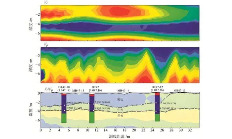
The above analysis will eventually produce seismic reflector profiles (like “underground radar images”), which will clearly show the geological structure of a certain range of hands (usually tens to hundreds of metres) and thus provide an advance forecast of the presence of adverse geological bodies such as faults, dissolved holes, abundant waters, etc., to provide the basis for adjustments to the engineering programme (e. G. Support reinforcements, drainage measures) and secure construction. The following is a map of the earthquake in the ground floor:
See video below for the subsurface seismic exploration experiment:
Ii. Typical applications for seismic wave detection
1. Tsp technology
Tsp technology is one of the most widely applied methods of seismic superpredictation in the current tunnel construction, and its workflow and rationale are closely linked to the seismic wave detection logic described above:
Systems: composed of seismometer hosts, wave detectors, blast sources (or mechanical seismic sources) and data-processing software. More than 24 perceptors are normally placed on both sides of the tunnel at a depth of 1. 5-2 m at a distance of 1. 5 m, forming observation arrays。
Workstream: smuggle seismic waves through small dose blasts (or hammers), resonators capture reflectors, software processing time generation - depth profiles. For example, when the reflection wave amplitude is suddenly increased, frequency is reduced and travel times are abnormally high, the presence of shredded bands or rich layers is often indicated。
Case of application: in the construction of a high iron tunnel, tsp detection revealed the presence of a p wave velocity drop zone (from 4,500 m/s to 2,800 m/s) in front of the palm (from 4,500 m/s) and, in combination with the amplitude enhancement of the reflect wave, determined to be a fracture strip, the construction party pre-empted the risk of landslides。
2. Joint detection techniques for geological radars and seismographs
The geological radar (ground penetering radar, gpr) is a non-destructive geophysical method for detecting underground media structures and identifying buried targets using high-frequency electromagnetic waves (microwaves). The core principle is similar to echo depth, but uses electromagnetic waves rather than acoustic waves。
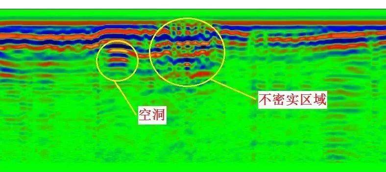
The core detection principle is the use of high-frequency pulse electromagnetic waves to penetrate the ground floor and reflect back into time profiles recorded in the media interface where electromagnetic properties mutate. The properties of the " anomaly" in the image and their spatial location information are analysed by the determination of the wave velocity and reflection period thresholds, the time depth conversion, etc. Spectrum response and poor underground electricity conditions (especially high water content) are among the most common constraints. The rationale for mine detection is as follows:
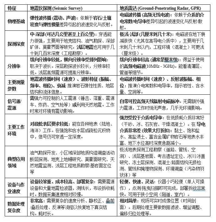
Seismometer and geological radar detection are important geophysical exploration methods. They vary significantly in their rationale, depth of application, resolution, application environment and so on。
A. Similarities:
1) similar rationale - reflect/reflect wave method:
Both are based on the principle of volatile transmission (one is elastic and one is electromagnetic)
The core method is reflection: the energy pulse is launched underground, and the transmission time and range of the signal (reflection wave) is received and analysed for reflection from different density/physical interfaces. Refraction waves can also be used。
It is necessary to know the speed of wave transmission in the medium (seismic speed vp/vs, electromagnetic speed v) to convert the time of transmission to depth (i. E. Depth = speed * time of transmission / 2)。
2) the purpose of the detection is similar: non-destructive detection of the target object, revealing the subsurface structure: identification of the stratum interface (base rock surface, tectonic surface, aquifer top plate, etc.), faults, wrinkles, rock variations, empty holes, ore bodies, etc。
3) data-processing dependency: professional data-processing software is required to process the raw data collected (filtration, gain adjustment, supercharge, deflection, inversion, etc.) to obtain an interpretable geological profile or model。
4) results are presented: time profiles are generated (vertical direction shows a two-way wave when twt moves). It needs to be converted to a depth profile using a speed model。
5) environmental impact: data quality is vulnerable to non-equilibrium factors such as surface topography fluctuations and the heterogeneity of subsurface media, requiring correction (e. G. Seismological correction of earthquakes, gpr topographic correction)。
6) cross-validation/joint application: in actual exploration, especially in complex geological surveys, the two are often used in conjunction with other methods (e. G. Gravity, magnetic, electrical resistance) to validate and supplement information (e. G. Shallow gpr, mid-deep seismic)。
Differences:
C. Joint detection techniques:
In order to improve the accuracy of forecasts under complex geological conditions, seismic instrumentation and geological radar (grp) are frequently used for joint detection, with the following characteristics:
1 technical complementarities: seismometers are good at detecting macro-geological structures (e. G., large faults) at 100-metre levels, while geological radars have a higher resolution of fine structures (e. G., crack networks, small dissolved holes) to shallow (0-30m)。
2 data integration method: calibrate the electromagnetic wave speed of the geological radar through seismic wave-speed inversion, superseding both detection profiles. For example, in a road tunnel, the seismometer found a wave-speed interface in front of 80m, and the geological radar further confirmed the presence of a dense crack zone in the 20m area near the interface, providing a precision target area for the reinforcement of the plume。
The choice of which method depends primarily on:
Depth of detection targets: deep search for oil for mining earthquakes; shallow surface piping, archaeology, base surface, engineering disease selection gpr (taking into account environmental electrical conductivity)。
2 resolution requires a fine structure (less than a metre-to-cm scale) and a shallow selection of the gpr in depth; large-scale layers, tectonics and earthquakes。
3 working environment (surface and underground): is the surface flat enough for large-scale deployment? How is underground conductivity? Time requirement? Earthquakes are more resilient and gprs are significantly limited but more light and fast. Urban concentration areas may be more convenient for gprs。
4 costs and targets: earthquake costs are usually much higher than gpr. Needs assessment project budget and needs focus。
Limitations of seismic wave detection techniques and directions for improvement
1. Existing technical limitations
1 inadequate resolution of complex geological formations: for thin geological formations of less than 5 m thickness (e. G., thin clamps dissolved holes), reflecting wave signals are prone to background noise and difficult to identify。
2 polylysis: the same seismic wave characteristics may lead to lower wave speeds in different geological bodies (e. G., rich water layers and shredded belts) and need to be interpreted in combination with geological survey data。
3 impact of construction interference: strong noise sources, such as tunnel blasts and mechanical vibrations, may lead to a decrease in reflective wave noise relative, especially during shallow detection。
2. Directions for technological improvement
1 multi-wave joint inversion: using p-wave, s-wave and face wave data, combined with trans-wave fragmentation (s-wave dilution when passing through a crack medium) to improve the accuracy of recognition of the development of the cracks. For example, a research team reduced the inverted error of the cavity angle from ±15° to ±5° through the s wave oscillation analysis。
2 artificial intelligence data processing: introduction of in-depth learning algorithms (e. G. Volume neural network cnn) for autotranslation of seismic profiles and intellectual recognition of faults, dissolved holes, etc. Through training in historical engineering data. A tunnel engineering application indicates that the accuracy of ai interpretation increased by 30 per cent over manual interpretation。
3 minimation and arrayization sensors: development of high-precision micromechanical systems (mems) wavers to achieve millimetre-level vibration capture and increase the resolution of the image of shallow geological bodies through intensive array deployment (e. G., range 0. 5 m)。
Future trends
As engineering progresses towards deep sea and deep burial, the following trends will be observed in the application of seismic wave detection techniques:
Three-dimensional dynamic imaging: simultaneous collection of data through multi-earthic sources - multi-prospectors arrays, combined with real-time deflection imaging techniques, construction of a three-dimensional geological model in front of the palm, increasing the spatial positioning accuracy of the adverse geological bodies from the rice to the amys。
Cross-scale monitoring integration: the integration of seismic instruments with technical data such as drilling periscopes, acoustic cts and the formation of a full-scale geological forecasting system for “macro-spectural cracks-micro-pores”, for example, in deep-laying tunnels, where faults are determined by seismic waves, and the development of cracks in the fault zone is observed by drilling television。
Intelligent early warning systems: integration of seismometer data into the construction security monitoring cloud platform, automatic activation of adverse geological warning through real-time analysis of reflective wave characterization changes (e. G. Amplitude mutations, wave-rate decay gradients) to achieve a shift from “ex post analysis” to “real-time early warning”。