In the spray-dry tower process for the production of ceramic bricks, the traditional method of dust removal is that of dust removal using cyclones, but the effect of this method is incomplete. In recent years, the need for cleaner production and energy-saving emission reductions has led to increased use of ffs by enterprises. Cyclone scrubbers are used as crude filters, and bag cleaners are used as fine filters, both of which go hand in hand. Despite the increase in inputs, the reduction of dust emissions to the atmosphere from spray-drying towers, while allowing for recycling of usable dusts, has had two effects。
2 pumper working principles and description
The bagders use a scrubbing needle filter as a filter (filtration core) with high aerobic performance and high dust removal efficiency. It is made of an empty filtration component (commonly referred to as a bag) in a cylinder wrapped in a metal skeleton, and several filtering components (figure 1 in three) are packed into a specially designed box, short of a gas tank pulse bag, as shown in figure 1. The bagber is made up of multiple such gas case pulse bags。
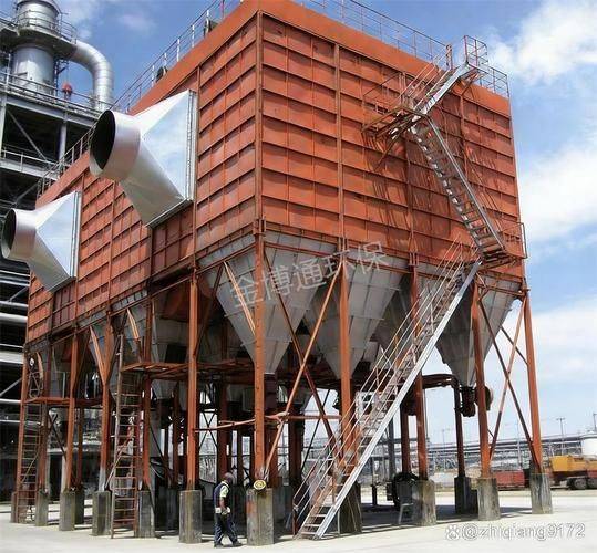
An airbox pulsed bag scrubber, using an anti-blowing method, not only cleanses general dust-sulphur-containing gases, but also treats dust-containing gases at an entry concentration of 1300 g/nm3. The water vapours contained in the flue gas, due to their high temperature, were at about 100°c and were in the initial gas state; the temperature was reduced after coming out of the spray tower, and the droplets were condensed into dust particles attached to the smoke, presenting a mist; and the dust particles were captured and collected when entering the gas tank's pulsed bag cleaners。
The dust removal process is as follows: for example, in one bag, the gas containing the dust is entered directly from the point of entry into the bag room of the gas tank; due to the gravitational drive of the negative wind press, the dust-bearing gas is removed from the outside and inside, from the bottom up, to overcome resistance and cross the filter core to reach the upper box; dust is blocked outside the filter component, small particles are adsorbed to the surface of the filter core and large particles fall directly into the grey coil below; the filtration gas containing microdust accumulates at the pulse lift valve and is released from the vent, at which point it is clean. This process is illustrated by the filtering state in figure 1, which is the dust-containing gas. When the filter reaches a certain time (or resistance reaches a predefined value), the ash removal process begins. The work process is as follows: the controller sends a signal that the pulse lift valve will be closed and the vent will be blocked; the compressed air pulse valve will be activated by a compressed air pump valve greater than 0. 5 mpa, which will be injected into the gas chamber; and it will expand rapidly into the filter and produce vibrations to remove dust from the surface of the outside of the filter and fall into the dust plume, as shown in the ash state in figure 1. Upon completion of this action (approximately 6-15s), the compressed air pulse valve is closed, the valve is lifted and the filter in the chamber is re-filtered。
The tail gas of the spray towers contains a large amount of dust and waste gases such as so2, which can be reduced to less than 40 mg/m3 by two orders of magnitude compared to the previous 8,000 mg/m3. The dust removed is clay dust that can be recycled。
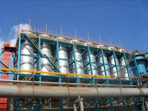
This paper contains a bag of 18 gas case pulse bags. Gasbox pulse bags require regular clean-up of dust from the core surface to prevent congestion. The ash is collected in the form of a box-by-pack clean-up, which is carried out in a compartment-by-box, alternately and as required until the end of the last chamber, which is a clean-up cycle. The pulsating blow width and ash cycle of the scrubber are carried out continuously by automatic ash removal control, thus ensuring the effectiveness of the ash。
3 control system design
During ash removal, the lifting pulse valve and the jet pulse valve shall be closely aligned. Its course of action is to break the lifting pulse valve and then open the jet pulse valve; the pressure test is performed in a few seconds; the jet pulse valve is then turned off and finally the lifting pulse valve is opened. The system output signal, which is to be severed or activated by an electromagnetic valve, controls the ash removal of each gas tank pulse bag. Such a large number of lost exports can be achieved by simplifying the volume of lost exports through arrays, by increasing the measures of the software directives and by not reducing their functionality, as shown in figure 2。
In this system, the siemens programmable controller s7-226 is accompanied by an extended module, em223, of which ka1-ka18 is the relay for control of pulse lift valves 1-18, and ka19-ka36 is the relay for control of pulse jet valves 1-18, all of which are indispensable. If these 36 relays are driven by 36 lost exports, they will be numerous. Since this paper uses the working characteristics of rotational ash clearance, the 18 pulse lifting valves have only one action at any one time, and the 18 pulse jet valves have only one action at any one time, and only 18 of the q1. 0 to q3. 3 are now used to drive 36 outbounds using arrays. For example, if the jet valve no. 2 ka20 action is to be achieved, it will only be possible to export q1. 0 and q3. 2 simultaneously during the process. The directive reads as follows:
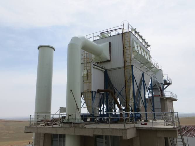
In the design of this system, plc sets the test entry points to be used to automatically detect the working condition of each bag, especially if the bag is broken or blocked. When a bag is broken, the pressure falls too quickly within seconds of the compressed air jet, and the pressure sheet detects a significant decrease in the pressure; the pressure table is too low to output a detection signal (e. G. Kl) to plc to alert and instruct plc for timely handling. The detection of over-pressure in a few seconds of compressed air jet means that the bag is blocked by dust, the pressure drops too slowly and the filtering capacity is poor, and the pressure sheet also outputs a detection signal (e. G. Kh) to plc to alert and instruct plc to process in a timely manner. So many input interfaces need to be streamlined. As shown in figure 3: this design requires only six input points: i3. 2, i3. 3 and i3. 6, i. 3. 7 and i 4. 4, i4. 5, to achieve a total of 36 input feedback signals with 18 bags of ultra-low and ultra-high pressure. For example: bag 5 broke, when the ash jet was used, the pressure was reduced too quickly and the pressure sheet was set at the minimum action limit; the input point i3. 3 of the input module could be captured through the ka5 and kl5 circuits to this failure; and the program software was used to distinguish the resulting alarm signal from the human interface。
Conclusion
Through the simplification of the control system, the author successfully designed and produced a control application system for bagging. Not only did it result in savings in hardware costs, but it also improved the reliability and stability of the system's work, with clear economic results。