
1. The purpose of electromagnetic compatibility studies: to eliminate or reduce natural and perceived electromagnetic interference, reduce its hazards, increase the resistance of equipment or systems to electromagnetic interference and ensure the electromagnetic compatibility of equipment or systems。
Electromagnetic pollution includes the effects of hazards to human health, such as radio frequency radiation, nuclear electromagnetic pulses and electrostatic interference, on the destruction of equipment or systems and on their safety and reliability。
3. What's the management agency for the electromagnetic spectrum? It is managed by a specialized agency, and our country is allocated and coordinated by the chinese radio management committee。
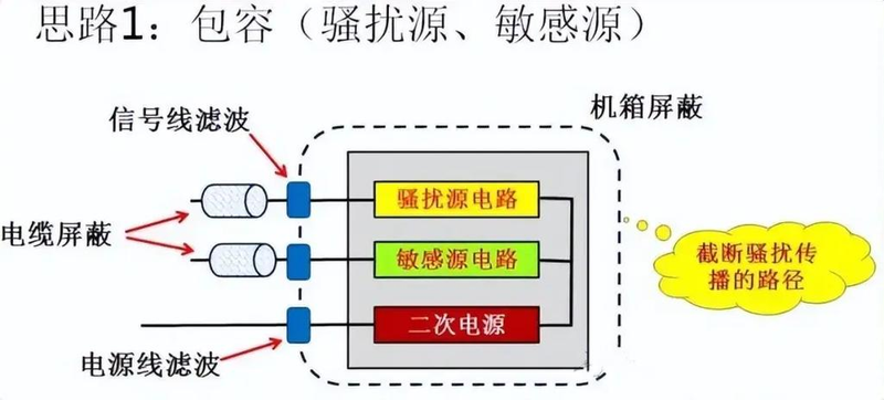
4. Basic measures to suppress electromagnetic interference: shielding, filtering, grounding and rational layout。
5. Characteristics of electromagnetic pulse signals: the electromagnetic pulse is a very serious source of electromagnetic interference, with a wide spectrum of coverage, field strength and wide range of effects, from which antennas, transmission lines, cables and various types of shielding cases can be perceived to generate powerful pulse frequency currents。
6- make an effective wireless condition: a, for a bipolar/unipolar antenna, the formation of an active antenna requires two electrodes or an electrodes and a geo-level. When each electrode is 1/4 wavelength, the antenna b, for a circuit-back antenna, should reduce the area of the circuit, or its sectoral circuit-backing effect should offset each other c, for a suture antenna, the maximum size of the gap should be reduced or wave-guided structures should be used to reduce radiation below its cut-off frequency。
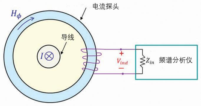
7. Modes of interference with circuits by radiomagnetic waves of space radiation: antenna coupling, conductive sensor coupling, closed circuit coupling。
8. Electrical shielding: eliminates or inhibits the coupling of the electric field or the turning field with the interference of the circuit。
Basic conditions for the realization of electrical shielding: full shielding and good grounding。
10. What are the different conditions for eliminating or inhibiting electrical field interference: a removes electrical field interference conditions: a complete well-connected shield conductor b suppresses the electric field: an incomplete well-blocked conductor。
11. Common measures to curb the disruption of the circuit field: use of well-connected and well-conductors to surround protected circuits as much as possible to shield the field。
12. Main measures to improve the shielding effect of the magnetic field: a high-magnetic conductivity material b increases the thickness of the shield c to avoid openings, and a two-layer shielding structure for gap d。
13. The main function of the filter is to limit the frequency band of the receiver so as to inhibit the useless signal without affecting the useful signal。
Common classification methods for filters: whether a contains the d-frequency feature of the active device according to the energy loss characteristics of the filter b in the electrical circuit。
15. Questions to be noted in connection with the installation of a power-line filter: the location of the installation of the a filter。
16. Draw a physical model of the electric capacity:
17. Draws three or more low-access filters and other basic circuit structures:
Site: means that the equipment or system is connected to "the earth"。
Purpose of ground: a establishes a low resistance route connected to the land, allows a direct flow of thunderstorms, static discharges, etc. From the ground, without affecting the normal operation of the equipment or system, and personal security b establishes a low resistance route between the equipment shell and the nearby metal conductor, and, when there is a leak in the equipment, does not connect to a public point or level all parts of the system that endangers the physical security of c equipment, in order to have a public participation level, eliminate the possible interference of the d barrier between the two suspended circuits, enable the shield to connect the filter to e and enable the filter filter to act as a deterrent to the signal circuits on the electric road pole f to reach the surface, in order to provide a signal return to the metal casings of the g-carrier, non-vital circuital vehicle on the aircraft, or the robotic body, in order to provide an electrical flow backway。
20. Methods of jamming the control of the site: floating, single-point, multi-point and mixed-point and multi-point sites。
Based on the concept of the map, indicate the local approach: a, single-point, b, multi-point, c, mixed。
Based on the graph concept of geo-functional analysis: a can use a single-point approach to prevent radiation and reduce resistance when frequencies are below 1 mhz or less than 120 lengths of the surface line, with a single-point line of connected and shared-point lines, which are divided into separate and single-point lines according to the wiring method. The latter applies to high-frequency situations because of the large number of surface lines, which are often shorter in complex b multiple-point geo-lines, but where multiple points cause back-routing interference that adversely affects the lower frequency, the mixed c is able to satisfy both short and open roads。
23. The location of the shielding layer of the shield can be shown in the following ways:
24. Commonly used methods to reduce low resistance: a is close to the ground by using multi-point approach to widen the signal of the c-units as long as possible。
25. In the grid and circuits, why there is frequent transient harassment: operation c malfunctioning of a thunder b switch
26. What conductive harassment often occurs in the electricity grid: power outages, frequency deviations, voltage falls, waves, voltage noise, waves, transients。
Characteristics of waves: for transient voltage with duration greater than 8. 4ms。
28. How transient harassment occurs in switch disconnection operations: arcs are generated during switch disconnections and closures, electromagnetic harassment occurs in circuits and spaces, and interference with other equipment received in or near the same grid. A switch controls the presence of a sensory b-sensitive load in the circuit, after the switch has been broken, the charge differential c, which produces * at both ends of the switch, produces a charge discharge between the two ends of the switch with significant voltage differentials under certain conditions of air moisture, increasing the distance from the point of contact as the switch is opened and the required penetration pressure increases until it is impracticable。
29. Interception of transient harassment by switch operation: a reverses at both ends of the load and the uniode b reverses and connects the diode with electrical resistance。
30) reasons for electromagnetic harassment of electron installations: arc generated by a switch of electrical motivation, or back-to-back harassment with high frequency/transient voltage。
Electromagnetic harassment inhibition methods arising from electro-energy: a, when exposed to poorly or mechanical vibrations are apparent, is charged with the electric arc. In order to reduce harassment, it is necessary to maintain reliable contact with the electric arc, open normal, select a high-quality electric brush, keep the surface of the transformer purified, maintain appropriate pressure, in order to inhibit the arc, between the electric motors, and connect to the electrical capacity or to the electrical barrier b to curb the path of harassment transmission, and connect to the electrical capacity, provide a low resistance route, remove the path of the harassing current and suppress the resulting peak voltage。
32. Common appliances for curbing wave-disturbing: plumes of electric fire, metal oxidation sensitivity electrical resistance, transient silicon absorption of diodes。
General strategy for the control of electrostatic discharge: a prevents electrostatic charge generation b prevents discharge c from controlling discharge current paths。
34. The basic speciality of electrostatic discharge: during the time span between 0. 7 and 10ns, it peaks at tens of entanglements and may well exceed 100a。
35. In china, 3c certifications are mandatory: asab, emc-c import and export quality certification。
In the design of electronic circuits, in order to minimize emc interference, general attention should be paid to the following issues in the design of functional circuits: the selection of components in a: consideration of the structure and physical properties of a metaware; the design of b circuits, such as electricity, resistance, perception, transformers, integrated circuits: 1 power source, filtering, input/output separation; reduction of public resistance to 2 control units, barriers, transient harassment inhibiting 3 analogue circuits, location, distance from the source of harassment, limitation of work frequency, delay of rise/decrease time。
General principle to suppress the layout of circuit boards: a separates digital circuits from analogue circuits b and separates high, medium- and low-frequency circuits c with external signal transmissions from well-established circuits close to the connector's end d connector on the side of the circuit board。
38 - why electrical and electronic devices produce a concoction procession: flow control, speed control, switch power, etc. The non-linear properties of electrical electrons during their duration result in a coordinated current in the electrical system。
39. The main sources of electromagnetic harassment in electronic systems are: a high-pressure isolation switch and circuit breaker operation 2 thunderbolts and a system shortway 3 local discharge systems 4x2 switch operation 5 changes in loads and electrical voltage, interruptions, imbalances, harmonics and voltage changes resulting from harassment 6 generators and transformers, and the electric field and magnetic field 8 automation equipment generated around them, and the natural phenomena of radioturbation 9 from wireless equipment, such as lightning, electrostatic discharge, geomagnetic interference and nuclear electromagnetic pulses。
Measures to curb electromagnetic harassment of the electricity system include: for secondary cables placed close to high-voltage guidance lines, shielding measures should be taken, with a small external magnetic field allowing the shield to be grounded at a point, while in cases of serious external harassment, the shield should be 2 pairs of multiple cables at both ends, with instruction in the rational placement of cables and the selection of the right course to inhibit harassment, such as separating low-level signal cables from high-level cables, with secondary cables moving as radioactively as far as possible to reduce their alignment。
What are the general wiring principles for printing circuit boards? A circuit board should have shorter and thick lines, even lines b. Avoid parallel lines at long distances and increase the spacing of parallel lines appropriately。
Understanding of some pcb design principles because high-speed digital signals or clocks are a powerful source of harassment, the longer the line, the greater the likelihood of coupling to other parts. 2. Why can ' t a high frequency signal be separated from the print input output component: the line below the component forms a connection to its object or sense. 3. Why should all connectors be placed on the side of the board: the connectors tend to become part of a valid antenna and place them on the side of the printed circuit board in order to control the comodular voltage between connectors。


