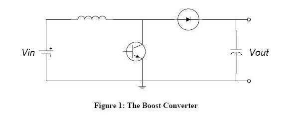
Basic circuit charts are shown in figure i:
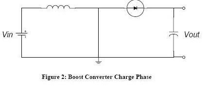
Assuming that the switch (triode or mos tube) has been broken for a long time, all the components are in ideal condition and the electric voltage equals input。
Here's two parts: charge and discharge
Charge process
During charging, the switch is closed (triode conduit), the equivalent circuit is shown in figure ii and the switch (triode) is replaced by a guide. At this point, the voltage stream is being injected. The diodes prevent the discharge of electric fluids to the ground. As inputs are direct currents, the electrical current increases linearly at a certain rate, which is related to the size of the sensor. As the electrons increase, some energy is stored。
Power discharge process
As illustrated, this is the equivalent circuit when the switch is off (closure of the triode). When the switch is off (triode cut-off), the current of the sensor will not immediately turn to zero, but rather slowly from the value at the time the charge is completed to zero, because the current of the sensor will be maintained. The original circuit had been disconnected, so the sensor had to be discharged through the new circuit, i. E. The sense had started charging the capacitor, and the voltage had increased at both ends, at which point the voltage had already exceeded the input voltage. Raise pressure over。
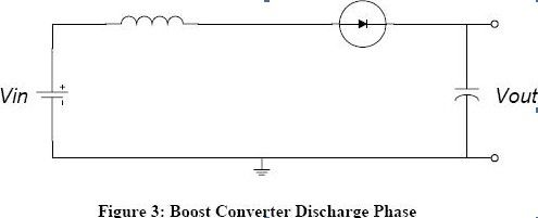
The lifting process is an energy transfer process of the sense. When charged, the sense absorbs energy, and when discharged, the sense releases energy。
If the capacity is large enough, a continuous current can be maintained at the end of the output。
If this break-up process is repeated over time, at both ends of the capacitation, the voltage above the input voltage is obtained。
Some of the additional 1aa low voltage, and the bottlenecks in the inflammation of the power and efficiency constraints of the insulation circuits are in the switch, the currents, and other losses (in electrical senses).
1. An electric sensor cannot use a magnet that is too small (can't hold the energy that it deserves) or too thin a line.
2. Most of the pipes use shortkiss, as you all do, are uncharacterized and run out about 10% of the total loss at 3. 3 v.
3 switches, here's the key, with plenty of enough to saturate, and a low, low-conducting pressure is the key to success... All in one volt, with more pipes running and no electricity coming out of them, and no more than 0. 2-0. 3v at which the current should be selected, with more than one combination if it cannot be achieved...
Four, how big is the current? Let's just be simple. It's more than that. Because of the inefficiency, this is the average, 3a for half-week power supply, and the actual current shape is 0 to 6a. It's suggested to use two tubes called 5a, actually 3a together.
We don't have any of the ready-made chips that integrate the power lines, so we're suggesting we use ground circuits to deal with ocean circuits.
When the switch is activated, the power is formed by a sensor-to-switch tube, and the current is converted into magnetic energy storage in the sense; when the switch is disabled, the magnetic energy in the sensor is converted to an electric right-hand positive on the left side of the sensor, and this voltage is stacked at the main end of the power source to form a circuit through the diode-load to complete the lifting function. In this case, the efficiency of the conversion has to be improved in three ways:
1. Minimize the resistance of turn-off circuits to turn electrical energy into magnetic energy as much as possible
(ii) minimize the resistance of the load circuits and enable as much magnetic energy as possible to be converted into electrical energy, while at the same time exhausting the circuits
3. Minimize the consumption of controlled circuits, since for conversion the consumption of controlled circuits is in a sense wasted and cannot be converted to energy on loads。
Specific calculations
Known parameters:
Input voltage: 12v-v
Output voltage: 18v-vo
Output current: 1a -- io
Output texture: 36mv ---vpp
Working frequency: 100 khz ---f
Table 1
At the time of stabilization, during each switch cycle, the increase in the electrons during the conductive period equals the decrease in the electrons during the shutdown, i. E. Vi*don/(f*l)=(vo+vd-vi)* (1-don)/(f*l)
Do=(vo+vd-vi)/(vo+vd) with parameters, don= 0. 572
2. Electromagnetics
First, the initial electrical current during each switch cycle is equal to the telepathic sense at the time of output. Volume
The value is vi* (1-don)/(f*2*io) and the parameters are brought in, lx=38. 5uh,
Deltai = vi*don/(l*f), parameters brought, deltai = 1. 1a
When the sense is less than the value lx, the output thread changes more markedly with the increase in the sense
When a sense is greater than this value lx, the output texture is almost non-reduced with the increase in the amount of the sensor, since the increase in the sense reduces magnetic deflation, taking into account other aspects such as input fluctuations that affect l=60uh
Deltai = vi*don/(l*f) with parameters, deltai = 0. 72a
I1 = io(1-don)-1/2* deltai, i2 = io/(1-don)+(1/2)*deltai
Parameters brought, i1 = 1. 2a, i2 = 1. 92a
3. Output capacitor:
In this case, the esr can ignore the fact that it's a bit of ceramic
C=io*don/(f*vpp) with parameters in
C = 99. 5uf, 3 33uf/25v ceramic conjunction
4. Magnetic rings and diameter:
The magnetic ring manual selects the suitable magnetic ring if the magnetic ring is unsaturated when it corresponds to the peak current i2 = 1. 92a
Irms^2=1/3)* (i1^2+i^2-i1*i2), parameter in, irms=1. 6a
Select the path by this current efficiency and working frequency
Other parameters:
Electricity: l as a percentage of empty:don
Initial current: i1 peak current: i2 wire current: irms
Output capacitor: c changes in current: deltai whole pipe pressure reduction: vd