Second, what is the working method of energy-saving lamps? According to industry experts, energy-saving lamps are mainly heating the lamp fuses through ballasts, which begin to emit electrons at approximately 1160 k temperatures (because some electro-powder has been painted on the light), electro-crash atoms generate non-flexible collisions, energy is obtained after the americ atoms have collided and the mercury atoms have hit the mercury atoms, emit ion after absorbing energy, emit uv rays of 253. 7 nm, uv fluorescent light, as fluorescent lights work at temperatures around 1160 k and are much lower than 2,200 k-2700 k, so their lifetime has also increased significantly, reaching more than 5,000 hours, as it does not have an electrical heat effect like white incandescent lamps, and the energy conversion of the fluorescent light is very efficient, reaching more than 50 flow per wat。
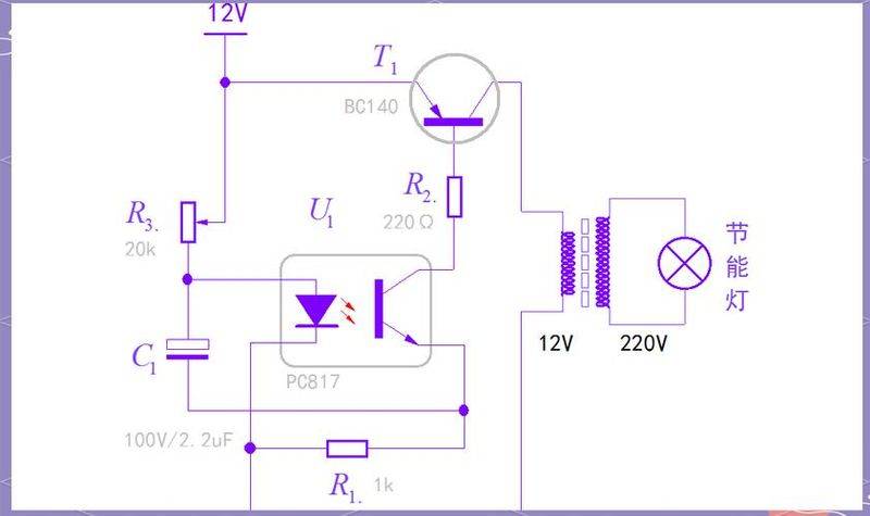
The energy-efficient light circuits are functionally divided into four sections: power circuits, start-up circuits, high-frequency self-introduced oscillation circuits and co-ordinated circuits. A brief introduction to the workings of energy-efficient light circuits is provided below in conjunction with circuits。
The municipal power source is a direct current voltage of around 300 v after a complete d1-d4 stream and a c1 filter。
The r6c7d9 is a start-up circuit, with currents running through the r6-c7 charge, and when the c7 two-end voltage is charged to the turning voltage voltage of d9, the diode d9 conduit is triggered, and the c7 is discharged via d9 to the tripolar t2-based poles, enabling the t2 conductor to saturate and conductivity quickly。
A high-frequency (hf) self-resilient oscillation circuit consisting of t1, t2, c4, c2, hf transformers and l, which is charged to c4c2 at the end of the t2 connection. Recharged currents in la, which flow through the primary loop of the high frequency transformer, are gradually increasing, and when la currents increase to a certain extent, the transformer's core is saturated, the c4 charge is no longer increased, and the flow through l begins to decrease. At this point, the backsliding of the voltage polarity played by lb in the sub-circle changed, making the vibrating motor positive in the lc, and the vibrating motor positive negative in the lb, forcing t2 to turn from guidance to deadline and t1 from cut-off to guidance. C4 begins to discharge, and when the discharge is increased to a certain level, the transformer's magnetic core becomes saturated, leading to a further change in the polarity of the lb, lc and the direction of the sensory dynamics on the lb is positive and negative; the direction on the lc is positive and negative, which in turn forces t2 to turn from a cut-off to a conductor and t1 to a cut-off, so that t1 and t2 control the hf transformer recommencing/cut-off next week, creating high frequency oscillation and providing high frequency voltage power to the lamp tube。
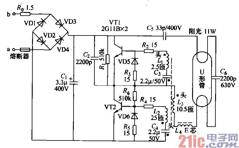
To meet the voltage required to activate the lighting tubes, circuits have been set up with interconnectivity circuits consisting mainly of components such as c2 and l. The roles of d6 and d7 are, respectively, to prevent reverse peak voltage through tti and t2. R3, r4 are negative feedback electrical resistance for tl, t2 flow protection。