
What's a schmidt trigger
The schmidt trigger is a slow comparator circuit, which is achieved by applying positive feedback to the comparator or the same input of the differential amplifier. The schmidt trigger uses two different input thresholds to avoid noise in the input signal. The role of this double threshold is called lag. The schmidt trigger was invented by american scientist otto schmidt in 1934. The normal comparator contains only one threshold signal. It compares the threshold signals with the input signals. However, if the input signal has noise, it may affect the output signal。
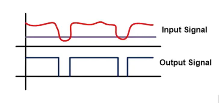
Impact of noise on output
In the above figure, the input signal (v1) crosses the reference signal (v2) level because of the noise in position a and b. During this period, v1 is smaller than v2, with lower output. Therefore, the output of the comparator is influenced by the noise in the input signal. And the comparator is protected from noise. The “trigger” in the name “schmidt trigger” derives from the fact that the output retains its value until the input changes sufficiently to “trigger” the change。
How does the schmidt trigger work
Schmidt triggers effectively handle noise input signals using two different thresholds (up-threshold (vut) and down-threshold (vlt)). The schmidt trigger is kept low output until the upper threshold (vut) is reached. It then transitions to a high output and continues until the input falls below the lower threshold (vlt)。
Let's take an example of how the schmidt trigger works. Here, we assume the initial input is zero。
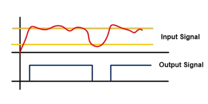
The noise effect of the schmidt trigger
Here, we assume that the initial input signal is zero and increases gradually, as shown above. The output signal of the schmidt trigger is kept low until point a. At point a, enter a signal over the threshold upper limit (vut) level and send a high output signal. The output signal remains high, until point b. At point b, enter a signal through the lower limit threshold. This makes the output signal low. Similarly, at point c, the output is high level when the input signal exceeds the upper limit threshold. In this case, we can see that input signals are noisy. But the noise is not affected by the output signal。
Schmidt triggers the circuit
Schmidt trigger circuits can be designed using an operation amplifier and transistor and classified accordingly。
L schmidt trigger based on an operation amplifier
L schmidt trigger based on transistor
Schmidt trigger based on an operation amplifier
Schmidt trigger circuits can be designed in two ways using an operation amplifier. If the input signal is connected to the reverse phase of the operation amplifier, it is called the reverse schmid trigger. If the input signal is connected to the same point of operation of the amplifier, it is called the same schmidt trigger。
Turn the schmidt trigger back
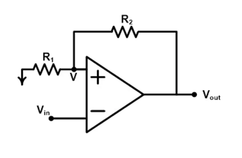
In the back-schmid trigger, enter the reverse-end that connects to the operation amplifier, providing positive feedback from the output to the input end, thereby enhancing stability。
Turn the schmidt trigger back
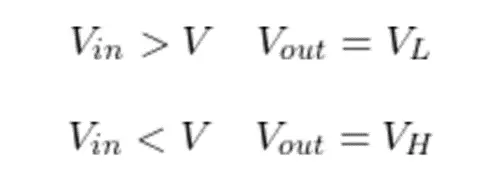
Now let's get to the point where the circuit works. At point a, the voltage is v and the voltage (input) is vin. If the voltage is greater than v, the circuit output will be low. If the voltage is less than v, the circuit output will be high。
Now, calculate the equation of the v。
This post is part of our special coverage syria protests 2011
Now, let's fake the output of the met trigger to the high level. In this case
So from the equation above
When the input signal is greater than v1, the output of the schmidt trigger will become low level. So v1 is the threshold maximum voltage
The output will remain low until the input signal is less than v. When schmidt's trigger's output is low, in this case
Now, the output remains high until the input signal is less than v2. Therefore, v2 is called the lower limit voltage (vlt type).
Same schmidt trigger
In the same schmidt trigger, enter the same root that is applied to the compute amplifier, with positive feedback from output to input, thus ensuring high output stability. Backends are attached for reference。
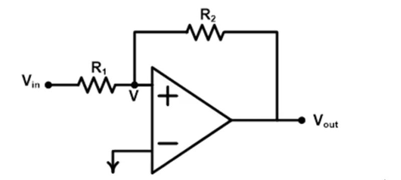
Same schmidt trigger
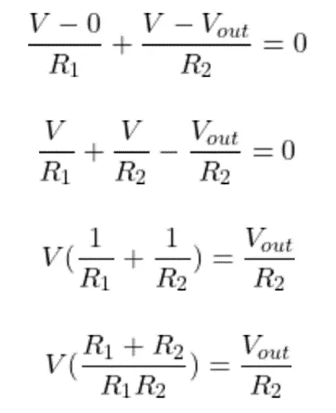
In this circuit, when voltage v is greater than zero, the output of the schmidt trigger will become high level. When the voltage v is less than zero, the output will be low。
Now, let's find the equation of voltage v. To that end, we apply kcl to that node。
Now, it is assumed that the output of the algorithm amplifier is low. So the output voltage of the schmidt trigger is vl. Voltage v equals v1.
In this case
From the equation above
When voltage v1 is greater than zero, the output will be high. In this case
When the above conditions are met, the output becomes higher. Therefore, the equation gives a threshold maximum voltage
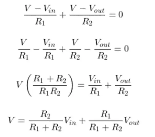
Now the output of the false facility's mitter trigger is high level. V equals v2.
According to the equation of voltage v
When the voltage v is used, the output of the schmidt trigger will turn to a low level of 2 less than zero. In this case
The upper form gives a lower limit voltage.
Schmidt trigger based on transistor
Schmidt trigger circuits can be designed with the help of two transistors. A chart of the circuits of the smith trigger based on transistor is shown below。
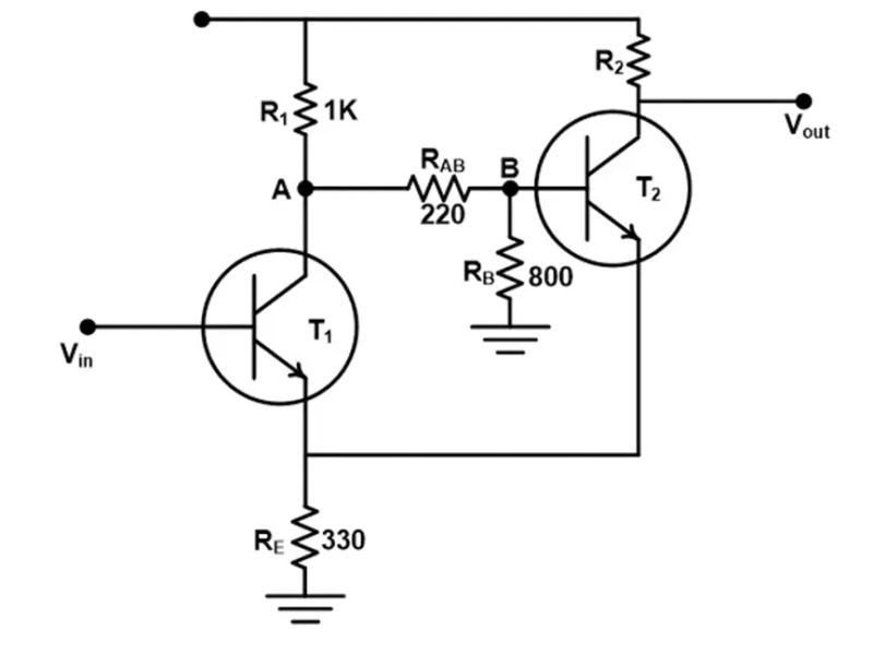
Schmidt trigger based on transistor
V in = input voltage
Decision v = base voltage = 5v
Suppose at the beginning, input the voltage vin to zero. Enter voltage to provide a base pole for transistor t1. Therefore, in this case, transistor t1 operates in the cut-off area and remains unconducted。
V one and vb are node voltage. Base voltage is 5v. So we can calculate the value of a v and a vb according to the subpressor rule。
The voltage vb is given to transistor t's base pole 2. It's 1. 98v. So transistor t2 is commanding. Therefore, the output of the schmidt trigger is low. The pressure drop at the launch pole is approximately 0. 7 v. Therefore, transistor voltage is very much 1. 28v。
The transistor t's launch pole 2 is connected to the transistor t's launch pole 1. Accordingly, the two transistor tubes work under the same level of 1. 28 v. This means that transistor t1 will run when the input voltage is greater than 1. 28 v or 1. 98 v (1. 28 v + 0. 7 v). Now we're going to input more than 1. 98 v, and transistor t1 will start. This could cause the transistor t-matrix to drop by 2。
Enter a voltage drop. Transistor t1 will be severed when input voltage less than 0. 7 v and 1. 28 v. In this case, the transistor t2 receives sufficient voltage from the baseline voltage, which will open. This makes schmidt's trigger output low. Thus, in this case, we have two thresholds, a lower threshold of 1. 28 v and a higher threshold of 1. 98 v。
Schmidt trigger oscillator
Schmidt triggers can be used as oscillators by connecting individual rc integrated circuits. Schmitt's circuit map of the trigger oscillator is shown below。
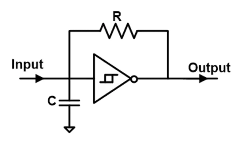
Schmidt trigger oscillator
The output of the circuit is a continuous square wave. The frequency of the wave shape depends on the r, c and schmidt trigger thresholds。
Of which k is a constant with a range between 0. 2 and 1。
Cmos schmidt trigger
A simple signal reverse circuit gives an output signal contrary to the input signal. For example, for simple reverse circuits, if the input signal is high, the output signal is low. However, if the input signal has a peak (noise), the output signal will react to the peak. We don't want it. Therefore, the cmos schmidt trigger was used。
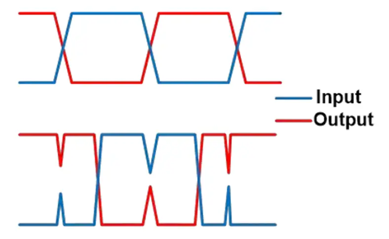
Simple signals reverse the wave shape of the circuit
In the first wave shape, the input signal has no noise. So the output is perfect. But in the second picture, the input signal has some noise. The output also reacts to this noise. In order to avoid this situation, the cmos schmidt trigger was used. The chart below shows the structure of the ccos schmidt trigger. The ccos schmidt trigger consists of six transistors, including pmos and nmos transistor。
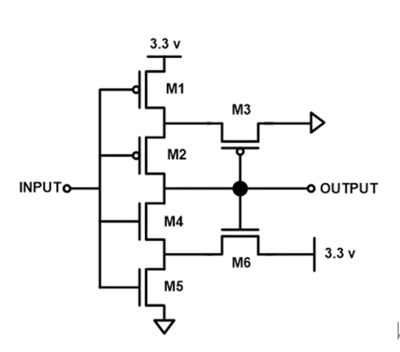
Cmos schmidt trigger
First of all, we need to know what is pmos and nmos transistor? The symbols of pmos and nmos transistor tubes are shown in the figure below。
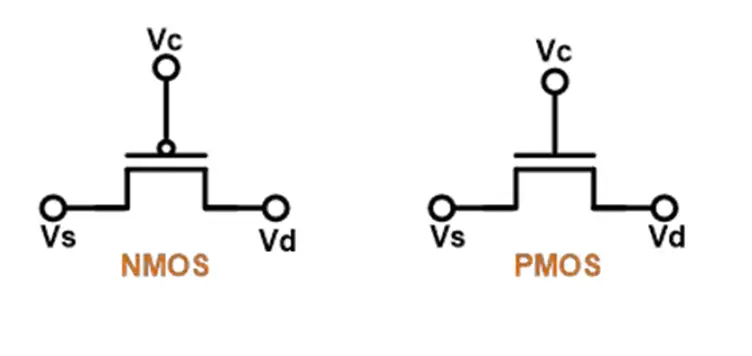
Pmos and nmos transistor
Nmos transistor conduits when vg is greater than vs or vd. When vg is less than vs or vd, pmos transistor conduit. In the ccos schmidt trigger, a pmos and a nmos transistor were added to a simple reverse circuit. In the first case, input voltage is high. In this case, the pn transistor is wired and the nn transistor is closed. It creates a ground path for node a. The output of the ccos schmidt trigger will therefore be zero. In the second case, input voltage is high. In this case, nn transistor conductor, pn transistor shut down. It will create a path to voltage v dd node b (high). Therefore, the output of the ccos schmidt trigger will be high level。
Schmidt trigger application
The application of the schmidt trigger is as follows:
L schmidt triggers are used to transform sine and triangulation waves into square waves。
L the most important use of the schmidt trigger is to eliminate noise in digital circuits。
L it also serves as a function generator。
I used to achieve oscillators。
L schmidt trigger with rc circuits used as a switch to shake。


