Hello! I'm chang! I'll be here every day to bring you up to date, and every single piece will be dry; if you think it's useful for your life, just ask for attention
In modern industrial production scenes, frequency transformers have become a core electrical control component essential for electric velocity and energy efficiency control, wind pumps, flow-line conveyor belts in small factories, large enough for machine-bed processing equipment, material lifting machines, and almost all equipment that relies on electric power for operation will be re-engineered with a transmission. In the first-line electrician community, there has been a widespread problem, with many young electricians entering for two to three years, who have acquired a strange type of frequency variant, unable to do anything about the hundreds of pages of parameters statements, randomly altering several of the more speed-reducing parameters, either getting power on the equipment directly over-stretch protection, or being unable to start the power, shaking and retracing for more than half a day without allowing the equipment to function properly and delaying the production of the workshop。
Following visits to several industrial parks, senior electricians with more than two decades of on-site practical experience have come to the conclusion of a standardized three-step commissioning process, which is free of brand barriers and which can be applied to the logical completion of base parameter configurations, both in terms of national production and in terms of imported high-end machines, and which, according to industry protection statistics, can stabilize more than 90 per cent of conventional industrial equipment in a suitable market. Many teachers are quick and steady in handling the debugging of the frequency transformer, not by remembering hundreds of parameter codes, but by strictly following this sequence and circumventing the various failures caused by the mismatch between the parameters at the root. In conjunction with the latest debugging of control equipment in 2026, the following is the complete dismantling of the exercise programme, while supplementing the error and optimization techniques that can easily be stepped on during the debugging process, which can be used directly by new electrician apprentices or maintenance staff who regularly handle electrical control failures。
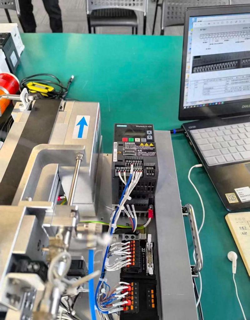
First step: precision entry of original parameters for the emulation of the electrical device and completion of initial calibration of the frequency transformer
The root causes of the failure of debugging the vast majority of the mutators are the entry of the initial parameters, and when many newcomers have access to the equipment, they skip this step to match the electrical parameters and directly adjust the functional settings associated with the start-up, speed-up, subsequent problems of overload, overflow, low-speed rectangular deficiencies, which are inevitable. In essence, the transformer is a device that controls the speed of the electrical transmission by changing the frequency of the output source, and only if the underlying data and the actual hardware specifications of the internal power are fully matched, the chip will be able to accurately calculate the output voltage, current values and ensure the smooth operation of the electric generator, which is the most basic and inoperable step of the entire debugging process。
Prior to the formal entry of the parameters, the recovery of the plant setting on the frequency transformer is required, a step that is easily ignored. If the frequency transformer was previously used in other equipment, the data on the parameters of the previous generator were retained internally, there would be a hardware fit conflict if the old parameters were used directly. Once the control panel had found the initialization parameter code and confirmed the execution of the compound, all functional settings would return to the default state of the plant, amounting to emptying the equipment's memory and preparing for the new configuration. The compound code of the different brand transformer is not the same, but the fast debug steering panel on the front page of the instruction book will mark the restoration of the plant's fast-track key combination, which will be followed by a guide operation, once after the reset has been completed, and will be effective。
This is followed by the recording of five core parameters by word, i. E., rated power, rated voltage, rated work current, rated frequency, rated speed, some high-precision performance machines, which indicate a power factor, and the corresponding values, which are filled in simultaneously, so that the units are consistent with the variable panel, and do not involve conversion errors in the units. The general rated specifications for the three-phase general power units are 380 volts and 50 hertz, but the parameters of the non-standardized electric power plant and the specialized radios for the conversion frequency are different and cannot be applied directly to the general default values, and the error of the parameters exceeds 2 per cent, leading to an abnormal operation。
Once the underlying parameters have been incorporated, a control model suitable for the current equipment needs to be selected, which is also the key option for determining the stability of subsequent operations. V/f pressure-to-frequency control mode, which allows simultaneous increase in operational resistance only when the speed of equipment is increased by wind adapters, pumps, etc., is less energy-consuming and the parameters are less difficult to debug; non-sensor vector-control mode, suitable for a constant rectangular load such as a conveyor belt, mixer, main axis of the machine bed, requires a stable output twister for the entire journey, which, even in low-speed operating conditions, ensures sufficient power and is the most commonly used control option for the workshop flow line equipment; closed-ring vector control with encoders, which is used only on high-precision processing equipment, lifting equipment, is completely less difficult to use; and redundant functional set-up only increases the difficulty of trialing。
Once this set of basic configurations has been completed, the core of the first step has been completed, and many electricians have omitted steps, which seem to have saved more than a dozen minutes, and it is the most efficient way to process it with strict process calibration of the electrical base data, which often takes hours to follow up on the failure。
Ii. Second step: implementation of self-learning recognition of electrical parameters to allow for the autonomous adaptation of frequencies to hardware characteristics
Many people mistakenly think that after filling out the label parameters, the transformer can fit the electrician perfectly. In fact, the labels are only standard theoretical values. The electrician surrounds electrical resistance, senses, and rotors resist these internal physical parameters. Each device has a slight deviation. In order for the transducer to be accurate, it is necessary to activate its own self-learning recognition function, which is the key link to the old electrician’s three-step programme, which is the most easily missed operation。
The self-learning of the variable is divided into the static recognition and dynamic recognition models, which do not require electric rotation throughout the static identification process, and the equipment remains static to complete the round-trip resistance data collection, which is suited to the conditions in the field that make it difficult to remove loads and is the most frequently used mode of daily debugging; dynamic recognition requires the operation of the machine in space, the complete collection of operational data across the full-turn speed zone, and the matching of processing equipment with a high rate of retrofit accuracy, with a preference for dynamic self-learning if field conditions permit。
Before self-learning starts, it is important to disconnect the connection structure between the electric and production loads, even with static identification, and not with a load running program, and additional mechanical resistance can interfere with data collection and lead to the eventual identification of a distortion. When it is confirmed that the connection is strong and that no one is close to the rotary component, the control panel finds the electrical parameter recognition starter button, and then presses the frequency, which will automatically output and test the current, and the process is usually in the range of dozens of seconds to two minutes, without interruptions, without artificial interruptions, waiting for the panel hints to be identified, represents that the transformer has independently stored the exclusive operation data of the machine。
Once identified, it is possible to switch to panel local control mode, where the space-borne point is activated to disable the generator, to observe whether the operation is stable, and whether there are problems of vibration, acousticity and slowness. If there is a clear shaking, the approximate rate is an entry error for the base sign parameter, and the first step needs to be returned to re-check the values and re-exact the identification procedure; the air-borne operation is smooth and smooth, allowing for the next step in the optimization of the operational parameters, and the entire process is gradual and without confusion。
The effect of this step would be to complete a deep match between the variable and the electric power, just as the blue teeth match between smart devices. Only the parameters of recognition, subsequent adjustment and speed reduction, protection thresholds, can achieve the desired results, skip the identification steps, and all subsequent parameter adjustments are surface modifications and fail to address the bottom of hardware suitability。
Iii. Step 3: final debugging with protection thresholds to optimize operating parameters based on load condition
After the first two core steps have been completed, a stable match has been achieved between the transformer and the electric power, the last being the combination of the actual load type of the equipment, the target setting plus the speed reduction time, the operating frequency range, and the various protection limits, which directly determine whether the equipment is capable of stabilizing long-term production, the different types of production equipment, and the parameter setting criteria are clearly differentiated and can fit more than 90% of the regular work profile according to load properties。
What needs to be finalized first is the acceleration and deceleration time, which is also the most frequent parameter to be modified in the day-to-day debugging and which is also the main incentive for overflow and over-pressure failure. Accelerator time represents the length of the time that the electric power rises from zero hertz to set the maximum frequency, and the duration of the deceleration is the length of the equipment from the working frequency drop-off, the greater the inertiality, and the length of the time required. The use requirement can be met by a light-intensity rectangular load, such as wind, water pumps, which accelerates the setting of three seconds and slows the setting of two seconds; a constant rectangular load, such as a general flow line conveyor belt, a light mixer, which integrates the retrenchment for five to ten seconds; and a high-intensity load, such as a ball grinder, a centrifuge, a large-scale squeezer, which needs to be stretched to more than fifteen seconds at a reduced rate to avoid the activation of an instant current peak to trigger a protection jumper。
In addition to time values, it is possible to optimize the performance of the additional speed-reducing curve, which is a generic calibration and corresponds to the vast majority of flat-starting equipment; the s-type curve is more smoother and can effectively reduce mechanical shocks, suitable for precision material delivery, textile equipment; and the non-linear square curve, which specifically matches the winder water pumps, aligns the load resistance with the increased and larger characteristics of the speed of turnover and further reduces airborne energy consumption。
The frequency ranges of the equipment are then assigned, the maximum frequency and the lower frequency are set, the upper frequency is not exceeded by the rated frequency of the motor label, and the hypervelocity operation is prevented from damaging the bearings and circuits, the lower frequency is recommended not less than 10 hertz, the normal walker is operating for long periods of time at low frequency, and its own heat-dissemination efficiency is significantly reduced, and it is prone to overheating. At the same time, adjust the rectangular lifting parameters as required, i. E. Low-speed voltage compensation, light-loading conditions with a reimbursement of 5 to 10 per cent, heavy-loading start-up equipment with an adjustment of about 15 per cent, which would cause electrical overheating, current over-standarding, and would require a better control range。
The last step was to set the full protective parameters, which would be equivalent to the installation of a safety shield for the entire electrical control system, first calibrating the electronic heat overload protection value, setting the protection threshold at 115 per cent of the rated electrical current, matching the conventional overload capacity of the electric power, and then closing the heat protection inside the transformer to avoid double-protecting the failure. Overflow protection, unpressure protection, and ground protection are all maintained out of the plant, with only checking the thresholds to match the current electricity voltage specifications, and with a high voltage voltage of the grid, suitable expansion between the voltage reserves can reduce the occurrence of unwarranted shutdowns。
Once all the parameters have been set, reloading the production load, full-loading operation, full-scale observation of a half-hour or so, to see if the frequency panel has a fail code alert, if the electrical shell temperature, the running noise is in normal range, no abnormality in the test operation, and the full set of frequency debugging is formally completed, followed by regular inspection of the parameter status。
Iv. The frequency debugging of the high frequency error zone is where newers are the most vulnerable. The pit
Even with a three-step process, a number of electricians are trapped in high-frequency error zones because of inherent operating habits, increasing the number of debugging times, combining four of the most likely errors in first-line maintenance cases, and significantly increasing the efficiency of debugging by circumventing ahead。
The first error zone, where the parameters of the other equipment were applied directly, the internal resistance data were completely different from those of different power, different models, even if the two equipment looked exactly the same and could not directly duplicate the parameters. There had been industrial park production lines that had failed at the same time because of the bulk application of the parameters, resulting in the simultaneous failure of multiple transformers, resulting in considerable production losses, and the only safe way to do so was for the single device to record individual placard parameters and perform self-learning recognition alone。
The second error zone, frequent changes in core parameters in operational status, and modification of key settings such as current, rectangular and speed reduction when the power is mounted, will result in sharp fluctuations in output power, which will easily trigger overflow protection. All significant parameter adjustments will need to be completed after power outages, with only frequency, outage control and such auxiliary parameters, which can be fine-tuned in an empty state。
The third error area, neglecting the heat-dispersion environment of the variable, many debugging equipment, operating after a certain period of time, had overheat-protected shut-downs, not a problem with parameter setting, but rather control of the dust pile in the cabinet, malfunctioning of the heat-dispersion fan, long-term operation of the transformer in a high-temperature environment, increasing the rate of ageing of the internal power module, and conducting daily inspections, in addition to checking parameters, of container dedusting and ventilation。
The fourth error zone, the random mixing of the control wire programme, and the new hands, when debugging, often confuses the off-site endpoint, analogue-to-speed lines and panel controls, following the basic debugging and then changes the layout of the control line to meet production needs, first to ensure that the ground panel controls function properly, then expand the external remote control function and gradually do not cause a problem with the logic of the connection。
Summary of concluding observations
The core logic of the three-step debugging programme, which combines more than 20 years of experience in the field of electric engineering and the debugging of the current equipment, is to follow the natural order of operation from hardware matching to self-identification to job optimization, fully aligning the bottom principles of the operation of the variable. The first step is to lock down the basic hardware parameters of the electric power and address the root causes of equipment suitability; the second step is to eliminate data deviations by self-learning to adapt the microphysical properties of the power distribution unit; and the third step is to optimize operational parameters and protection mechanisms in conjunction with load demand to guarantee stable production over the long term。
Many young electricians are too complex to think about debugging the frequency, reciting hundreds of parameter codes, while ignoring the importance of debugging the sequence, so long as the process is strictly adhered to, even if it is the first time they are exposed to a strange brand. The process of debugging the device was never to spell out the number of parameters, but to develop a standardized solution that followed the logic of running the device step by step, so that the problem could be solved at minimal time cost. It is also necessary to develop a standard operating habits, to maintain back-up records of parameters, and to remove archival parameters directly when follow-up equipment is overhauled and spare parts are replaced, avoiding the need to repeat the debugging workload。
What's the most difficult problem you've encountered in your day-to-day electrical work, debugging the frequency? Do you have any practical parameters set-up techniques that you've drawn up? Message exchanges in the comment area are welcome to share practical experiences and avoid problems on the debugging road。