Push drive circuits。
Tell me about igbt's turn-drive
1. This course is used to learn the igbt's push-drive circuit. This is the igbt, which does not exist in the industry, either as a mos tube or as a tripolar tube. Here's the symbol for the mos tube, this is the igbt triode. Here's the igbt polar c, and there's the e. R2 is a load, which can be a light bulb, an electric generator or a transformer。
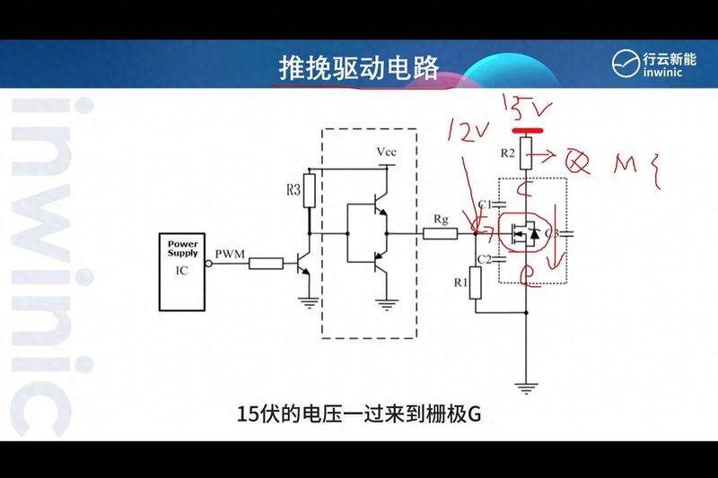
2. If grid g is provided with a voltage of more than 12 volts, it will be able to direct the ccd and the launch. In fact, in order to be more stable to trigger igbt or mos tubes, it is usually driven by 15 volts. As soon as the 15 volt volts come to the fence, they charge the parasitic c2. When it fills 15 volts, igbt will be able to achieve stability。
However, cpu output tends to be only 3. 3 volts, so the voltage is not sufficient to drive the igbt transit, and therefore a push drive circuit is added to the middle. Let's see how this circuit works。
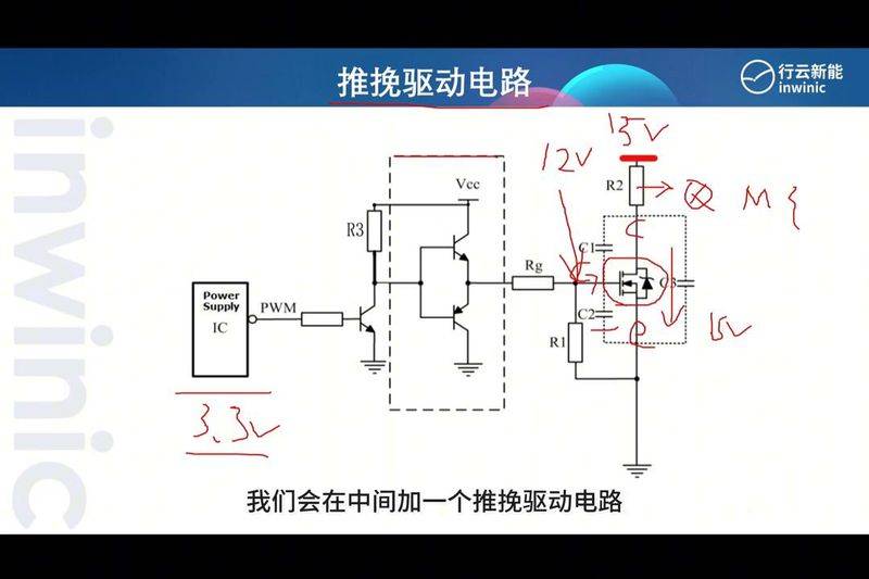
- first of all, cpu output a low level of electricity, resulting in a triode cut-off, so the voltage of this point is equal to the power voltage vcc. The 15 volts will give uplinks to the circuits, and the 15 volts will pass through the rgb, which is called the drive-back to the igbt。
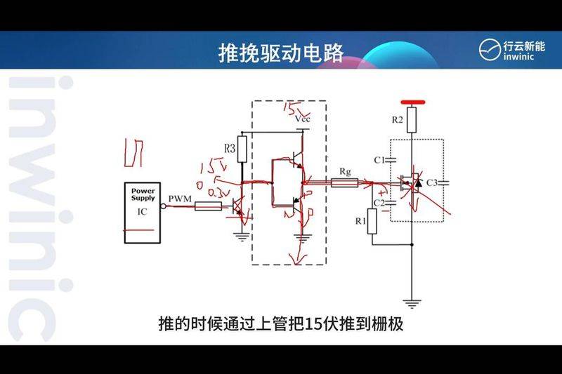
- here, cpu, what's the result of the high frequency output? If cpu output high frequency, 3. 3 volts will make the triode conductor. After the transfer, the 15 volts above are pulled down to 0 or 0. 3 volts. 0. 6 volt-low leveling will bring down the tripolar tube, which is the pnp conduit. The electricity of the parasite c2 will be quickly released through the sewer to the ground, thus bringing the igbt off, which is called a pushover. When you push, you push 15 volts through the upper tube to the end of the fence, and when you pull, you release through the lower tube。
Then let's see what rg and r1 do. The output end of the piping circuit to the mos or igbt grid has a certain length of conductor that creates an electrical sense, which creates a shock, causing the igbt to have such a shock during the trigger, which means that it will be unstable and, with this resistance, it will remove the energy of the shock. The value of this resistance is generally small, in the order of a dozen or dozens of euros. At the end of the igbt, because of the resistance, the energy through the tube could be limited, so at this upper end, a diode would actually be added, which is what drives the resistance。
5. In order to eliminate the shock, the r1 below is designed to prevent the accidental activation of the parasitic capacitor when it has electricity, since static power may also have the potential to charge the parasitic cap, so that the r1 can release the capacitor electricity. This is where the barrier value is usually larger, probably a thousand-european levels, and r1 and rg will form a neutral voltage, better to trigger igbt。
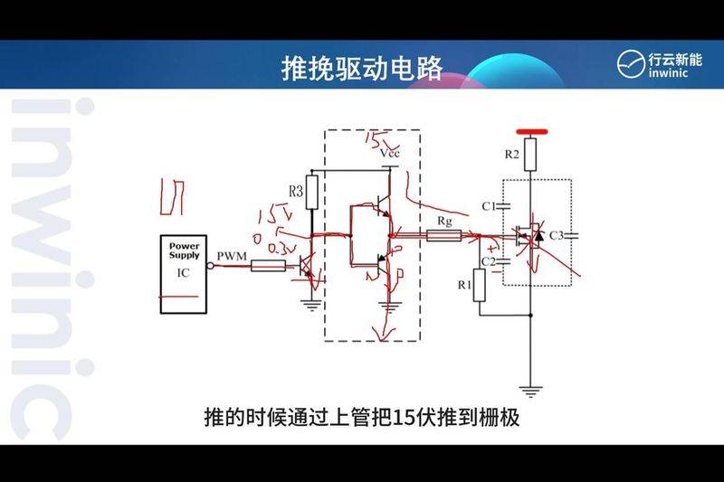
6. 15 the voltage must have been high through their two resistance sub-pressures. This is igbt's pull-on circuit。