Brief: the pwm output function of the f003 single machine has been tested in this paper in preparation for the design of the pump tank electrically driven circuit. The three-way pwm signal output of timer1 and timer3 was validated through the production of test circuit boards. The test found that the pb1, pb2 ports at timer1 and the pa5 ports at timer3 could normally export complementary pwm waves, but the pa3 ports at timer3 had anomalies. The available pwm output configurations were finalized, laying the foundation for the design of the subsequent step-in and current power drive circuits. In the course of the test, an unreasonable port setting in the initial design was also amended。
Keywords: f003, pwm
**ad\est\2026\april\stepmotordrvf003. Pcbdoc ***

Design circuits
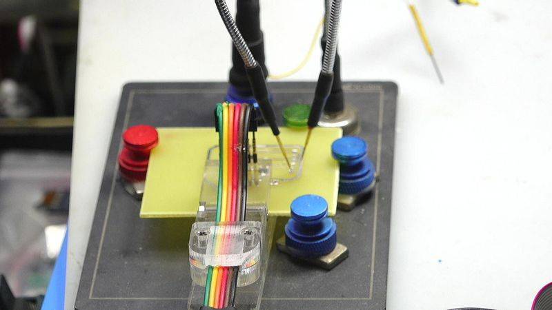
Today, in order to design an electric drive for a pump tank, which includes a step-by-step generator, and a direct current power generator, we're going to test the ability of the ciu32 to complete the drive. This requires the output of a two-way pwm and a two-way pwm signal, which contains two timers, t1 and t3, which can provide sufficient pwm channel output signals, as long as their pipes and feet are separated. First of all, the output of these pwm signals was tested through a test circuit class prior to the production of the official circuit. Then we build power circuits and now design a single-sided pcb to be tested by a one-minute board method。
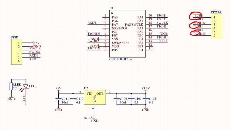
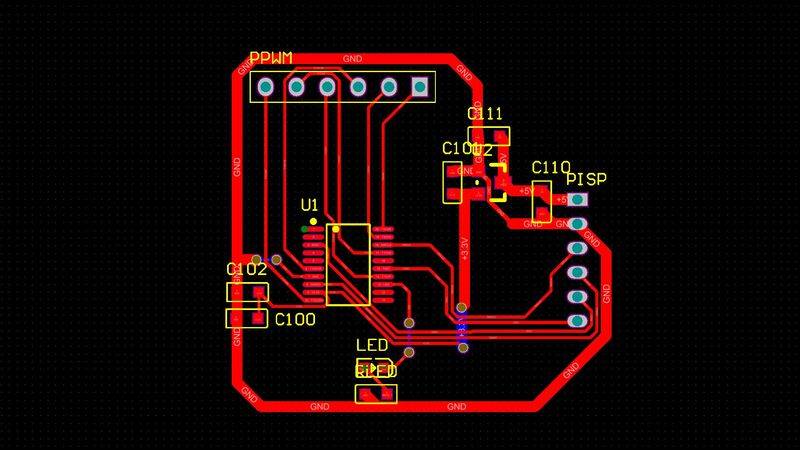
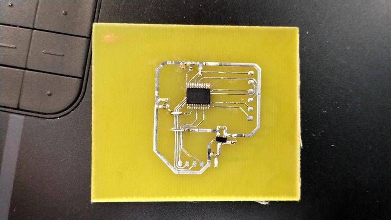
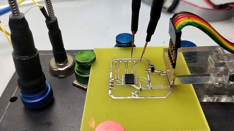
A minute later it was tested on circuit boards, which were perfect. Welded circuit boards, cleaned and ready for testing. The three-way pwm signal output of the circuit board is measured through external port statements. So we can check, through the oscilloscope, whether the three-way pwm wave-shaped foot signal, and the programming of the same。
Circuit tests
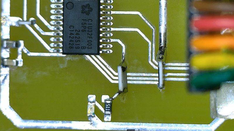
On the basis of the originally generated program framework, modify the program and download it to a single machine via the dap downloader after the keil environment is compiled. You can see that the single machine is now operational and can also receive the characters sent by the single machine through a serial. And down there we continue to measure whether the pwm signal on the single machine is normal。
Use oscilloscope to measure the output of the two-way pwm of timer1. It has a ratio of 1/8 all the way, and it can be seen that its positive input pulse corresponds to the default ratio, followed by a measurement of its complementary output pulse, which is its complementarity. The space ratio of the other two routes is set at 1:4 and the correct two-way output complementary pwm signals can be measured. The frequency of the signal is 734 hz, which is the corresponding output frequency after cpu's 48 mhz is 65536。
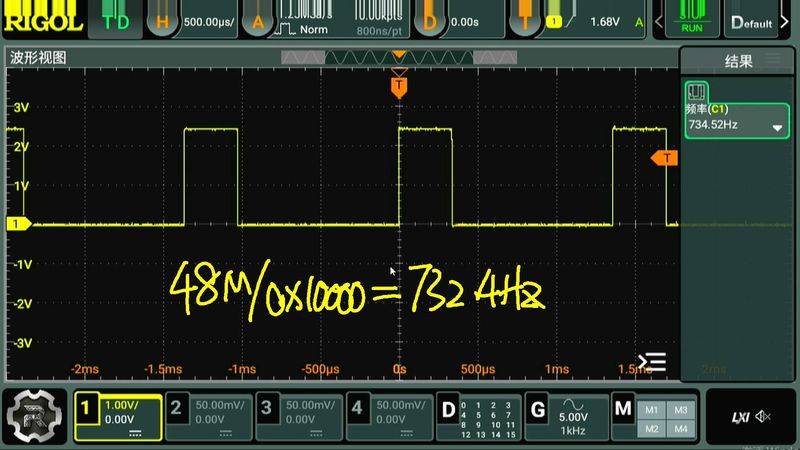
Test again the pwm output signal of timer3, which used the third and second channels of timer3 on the circuit board, but later found that it could not be exported in channel 3. The exact reasons are not yet known. The third channel output was changed to the first channel, the corresponding pa5 port. The wave shape of the output signal is now normal. Okay, so far, we have been able to complete the output test for the three pwm sets of f003 singles. This provides a test basis for the design of step-by-step circuit boards in the back。
Summary
This paper tested the port function for the pwm output of the f003 single machine, and the corresponding port configuration was found through the test, but it also found that the original setup was not reasonable, and in the initial design, there was no correct setup for the first port output of timer1. Use the pb1, pb2 port output, which is right for the timer1 third channel output. For the output of timer3, it was later found that the third channel for pa3 could not export the correct waveform for unknown reasons. And finally, it's the first channel of the pa5 to export normal pwm waves. This time we tested the pwm port output of the f003 single machine. And we're going to use it down here to design the drive circuits for step-in and power。