
Contents
General
The i/o port of the single machine is the channel through which the signal and the output signal are entered. The 8051 units have p0, p1, p2, p3 and 4 i/o ports, each with 8 quotations。
2. P0 port 2. 1 overview
The p0 port has a total of eight p0. 0 ~p0. 7 lures, which, in addition to being used as input and output guide, can also be used as an address/data bus guide when connected to the external memory. The internal circuit structure of the p0 port is the same for each of the thrusts, as shown in figure 1。
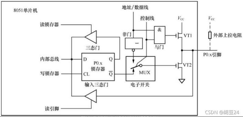
Figure 1 internal circuit structure at p0 port figure
2. 2 p0 port works as an output port
The following is an explanation of the need for a single machine to output high level "1" from p0. X. As shown in figure 1, the relevant circuits inside the single machine send "0 (low level)" through the control line to the control end of an input end and an electronic switch with the door, the "0" on the control line closes the door on one hand (i. E. "0" on the other end, regardless of the signal entered at the other end, the output is "0" on the other), the transistor vt1 fence is extremely "0" closed, and the signal from the address/data line cannot be transmitted through the door and the transistor vt1; the "0" side of the control line controls the electronic switch, leaving the electronic switch and the locker open
End connection. Cpu delivers high-level level "1" from the inner bus to the d-end of the locker, while sending the cl-end to the locker, and the d-end "1" immediately puts it in the lock and from q and
End output, d-end input '1, q-end output '1,
Peer output "0",
The end output "0" is delivered via an electronic switch to the fence of the transistor vt2 with the end of the vt2 and, as the vt1 is also closed and the p0x is suspended, there is a need to draw electrical resistance on the p0x mover and, at the end of the vt2, the p0x mover output high level。
The following is an explanation of the need for a single machine to output a high level "0" from a p0. X induced foot. As shown in figure 1, the relevant circuits inside the single machine send "0 (low level)" through the control line to the control end of an input end and an electronic switch with the door, the "0" on the control line closes the door on one hand (i. E. "0" on the other end, regardless of the signal entered at the other end, the output is "0" on the other), the transistor vt1 fence is extremely "0" closed, and the signal from the address/data line cannot be transmitted through the door and the transistor vt1; the "0" side of the control line controls the electronic switch, leaving the electronic switch and the locker open
End connection. Cpu delivers a high level "0" from the inner bus to the d end of the locker, while sending a cl signal to the cl end of the locker, and the "0" of the d end immediately inserts it in the lock and from q and
End output, d-end input "0", q-end output "0",
Peer output '1,
The end output "1" is delivered via an electronic switch to the fence of the transistor vt2, and the vt2 conductor is suspended because the vt1 is closed and the p0x is suspended, so the p0x is required to apply a drag on the p0x to the foot, and at the vt2 conductor, the p0. X to the foot output low level。
In general, when a single machine is required to use a p0 port as an output port, the internal cpu sends a control signal “0” to the door and an electronic switch that closes the door (the end of the transistor vt1 at the same time, the address/data line is separated from the output circuit), the electronic switch connects the locker to the output circuit, and then the cpu sends the data and writes the locker signal to the p0 port through the internal bus, and the data is exported from the point of entry at the p0 port through the locker, the electronic switch and the output circuit. When the p0 port is used as an output port, the upper transistor tube of the internal output circuit is closed (opening), and the leak of the lower transistor tube is open (known as a transistor opening), and therefore there is a need to pull resistance outside the p0 port entrance, otherwise it cannot be reliably exported "1" or "0"。
2. 3 p0 port as working principle for input port


