
The digital control system is abbreviated by the digital control system and is known as numerical coNtrol system, which performs some or all of the numerical control functions in accordance with the control procedures stored in the computer memory, with a dedicated computer system with interface circuits and server drives. The control of the movement of one or more mechanical devices is achieved through the use of digital commands consisting of numbers, words and symbols, which are usually controlled by mechanical quantities such as position, angle, speed and switches。
The digital control system and the associated automated products are mainly a numerically controlled machine-bed package. Digital-controlled machine-beds are integrated products of electromechanical integration resulting from the penetration of the traditional machine manufacturing industry by new technologies represented by digital-controlled systems: the machine-beds equipped with digital-controlled systems have significantly improved the accuracy, speed and efficiency of parts processing. This numerically controlled work mother machine is one of the important material bases for the modernization of state industry. The concept of numerical control (referred to as “numeric control” or “nc”) is to convert the processed mechanical parts, such as shape, size, etc., into numerical data command signals, to an electronic control device, which controls the movement of motor blades and processes the parts. In traditional manual machine processing, these processes need to be carried out manually, making it difficult to meet the processing requirements of complex parts, especially for multiple and small quantities of parts, which are inefficient and of poor precision. In 1952, the united states mit, in collaboration with parsons, invented the world's first third-coordinate number control bed. The control device consists of more than 2,000 electronic tubes of approximately one ordinary laboratory size. The server uses a small servo motor to control the speed of the liquid motor using the angle of the hydraulic motor shift. Its plug-in is carried by pulse multipliers. The successful development of the nc site marked the beginning of a new era of numerical control in the creation and mechanical manufacture of nc technology。
The precision machine bed number control system consists of cnc controllers, built-in plc controllers, switch power circuits, crt monitors, input output interfaces, pv encoders, etc. Switching power circuits are responsible for providing power to all parts of the entire machine-bed numerical control system. In places such as machine-bed workshops, where there is more power-based electrical equipment, in this complex electromagnetic environment, if the power switch is less reliable and the protective function is inadequate, it can cause the number-controlled machine-bed system to work abnormally, and it can easily cause major accidents such as motor vehicles. Therefore, high-reliability switches with various protective features are an important guarantee of the stability of the digitally controlled bed system. This paper focuses on the working principles and methods used to protect circuits from power switches in a machine-bed number control system, which, through its actual development, has led to a significant increase in the power stability of the system, a steady and reliable protection function, and a mass production requirement。
1 analysis of the rationale for the protection of circuits
The number of machine-bed switches contains circuits such as soft start protection, overpressure protection, overflow protection, and failure to voltage electricity protection。
(1) softly activated circuits
Since most of the back stages of power input into the whole-flow circuits are based on the use of an electric-capable filtering circuit filter, in the event of a power-column, there is often a current surge of tens or even hundreds of amperes, which is harmful, causing failure or even damage to the switch. The commonly used soft-start circuits include wave-screening protection consisting of controlled silicon and restricted current resistance, soft-start protection consisting of relay contact points, soft-started circuits consisting of negative temperature coefficient resistance, etc。
The system switch power uses a soft-activated circuit consisting of negative temperature coefficient resistance, which is simple, practical and reliable. As illustrated in figure 1, 220 v, following the l1 filtering concourse interference, the current produces around 300 volts of direct current voltage, rt resistance is thermally sensitive resistance with negative temperature coefficients, model m02-7. And when the power locks are in motion, the currents make heat-sensitive and heat-retarding, and the resistance is rapidly decreasing, and the output current voltage is building up, and it can be effective in preventing current shocks to power circuits, making the entire power half bridge stable。
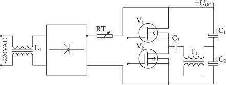
Figure 1 input soft-start circuits consisting of negative temperature coefficient resistance
At the start of the switch, since the pulse modem has not yet established a stable drive pulse, measures need to be taken to gradually build the drive pulse, which uses the more expensive pulse modem t l494. As illustrated in figure 2, the fourth foot of tl494 is dead zone control, which can provide secure dead zone time control for power transformers, or soft start control for drive chips. At the moment, no voltage was installed on capacitor c1, +5 v to deliver tl494:4 feet via capacitor c1, blocking the output pulse of the pulser. As the capacity c1 and the two end voltages gradually rise, the t l494:4 foot voltage gradually drops, and the pulse width expands. When the auxiliary power + 15 v fails, the third-stage tube v1 is rapidly delivered, and the +5 v voltage is delivered to the t l494:4 foot through the triode v1, cutting off the driver's pulse and stopping the switch from working without damage。
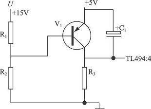
Figure 2 driving soft start and power protection using tl494:4 feet
(2) overpressure protection of circuits
Most of the usual digital signal-processing circuits use integrated door circuits in the ttl or ccos series. For ttl integrated door circuits, the working voltage may not be greater than 5. 5 v. The main transformer voltage + 5 v is protected in the switch power system with multiple circuits, such as +5 v, +15 v, -15 v, +24 v. The specific circuits are shown in figure 3。
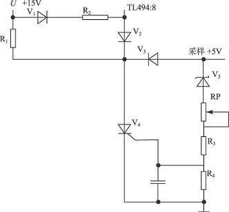
Figure 3 digital switch power overpressure protection circuits
Working principle: digitally controlled switch power is provided by auxiliary power source + 15 v to the controlled silicon v4 anode working voltage, and the actual output sample voltage is delivered to the steady voltage tube v5, and when the protective voltage threshold is exceeded + 5. 5 v, the output voltage triggers the controlled silicon v4 connection with a steady voltage tube, r3 and r4 fractional pressure, and the auxiliary power source + 15 v is used to block r1 and to cut the 8 foot power through the diode v2. Regulates the rp level, setting the output voltage protection threshold point。
(3) passage protection circuits
The working principles of this switch overflow protection circuit are shown in figure 4. The original side of transformer t1 is in the original side circuit of the main power transformer, and the original side length ratio of the reasonable transformer is selected by experiment, the original side current value of the sensor switch at the time the power is converted, the full flow of the diode v1 ~ v4, the r1 and c1 filter-poster rp. The larger the current, the greater the current flow of the current sample transformer, the lower the voltage of the rp central point of the power station, the lower the voltage of tl 494:2 feet, the higher the voltage of the tl 494:3 feet, the delivery of the pulser, the decreasing width of the tl 494 drive, and the consequent protection of the excess. The c4, c5, r10 feedback elements for the tl494 error amplifier in the figure make the magnification circuit stable。
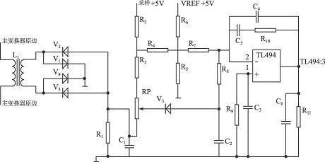
Figure 4 digital switch overflow protection circuits figure
(4) lack of pressure to protect circuits
When +5 v and pf (power fail) signals are used to compare, the pf signal needs to be maintained for at least 10 ms of time to store relevant information when +5 v falls off. The lack of pressure to protect circuits is shown in figure 5。
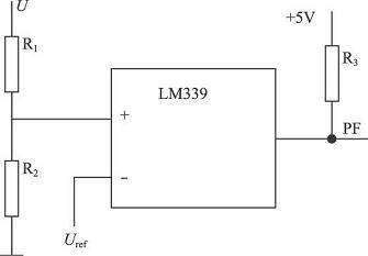
(a) power outage protection using lm339 voltage comparators
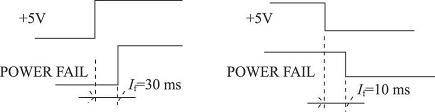
(b) time-series for power up and down
Figure 5 impairment protection circuits for digitally controlled switches
2. Protection of circuit debugging and realization
(1) soft start-up circuit debugging
Thermal-sensitized resistance softly activates the circuits, can be baked with iron branded to close thermal resistance to negative temperature coefficients, and can measure the change in their electrical resistance values using a mass-use watch, while counting and estimating their resistance rate, for a preliminary examination. Loads heat-sensitive resistance of different resistance values into circuits, uses oscilloscope high-pressure probes to test the high-voltage wave shape of the current circuit output when it is activated, compares the time when its voltage is built, and selects the appropriate negative temperature coefficient heat-sensitive electrical resistance。
(2) overpressure protection circuit debugging
Controllable silicon triggers in over-pressure protection circuits: 1) the trigger requires sufficient supply of trigger voltage and current. 2) when not triggered, the trigger end voltage shall be less than 0. 15 v ~ 0. 2 v, which should normally be offset by a negative pressure of 1 ~ 2 v to prevent an error. 3) the rise of the pulse is steep, preferably below 10us, to make the trigger accurate. 4) the pulse trigger must have a sufficient width, since the opening time of the controlled silicon is usually below 6us, the pulse width should be greater than 6us, preferably 20us~50us。
Overpressure protection circuit debugging: the output voltage is gradually transferred to 5. 5 v, the controllable silicon is tested on a single scale to trigger a polar voltage, while the oscilloscope is used to observe the tl494:8 foot, 11 foot wave shape of the chip, and the pressure is adjusted to protect the multi-ring rp until the circuit action, the drive waveform disappears, at which point the multi-ring rp spin button remains unchanged. And gradually lower the output voltage, and protect the circuits from action because it can be controlled by silicon. If the output voltage is raised to 5. 5 v, the protection of circuits will be repeated until the protection of circuits is secure。
(3) overflow protection circuit debugging
Overflow protection circuits select high-frequency iron oxygen magnet core ee12, with an original border electron sense of 0,013 mh and a side by side electron sense of 0. 74 mh. The switch +5 v maximum output current is 25a, intercepts a section of a 1. 2mm diameter of paint pack and takes a 0. 2-fold electrical resistance, connects this simulated load to the circuit, measures the excess current output ui, adjusts the overflow to protect the multi-ring pole, and the circuit begins to be protected at ui= -0. 57 v. Change the output simulation load, and repeat the current protection circuit parameters until the passover protects the circuit to be reliable。
Conclusion
By analysing and debugging the working principles of the power protection circuits of digitally controlled switches, the paper proposes a specific functional circuit for soft-start protection, over-pressure protection, and ultimately rationally sets the working parameters for each of the protection circuits, which allows the protection function of the switch to be stable and reliable, and the whole system to be upgraded, and the base for mass production of the control system。


