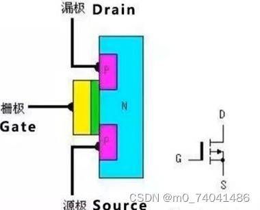
Nmos structure diagram
As shown in the figure below:
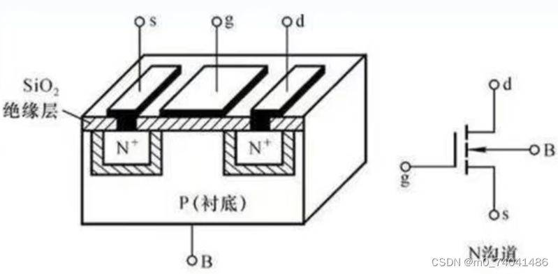
As shown in the figure above, nmos is a liner with a lower-blended p-silica, which uses the diffusion process to spread two high-blended n-areas (n+) on the liner, and to induce two om-exposure electrodes in this n-type zone, known as source polar (s) and leak polar (d). Covers a silica oxide (sio2) insulation layer on the liner surface between the source cavity, called a fence oxidation layer or a fence insulation, where the metallic aluminium layer is deposited and the electrodes are extracted as a fence (g). A om electrode is referred to as a lined electrode (b) from the base。
In the mos tube, the source provides the end of the carrier and the end of the carrier is missing. The nmos tube is typically connected to the lowest level of the circuit, while the pole is connected to the highest level of the circuit。
Two pn knots, two diodes, were formed between source s and leakage d and liner。
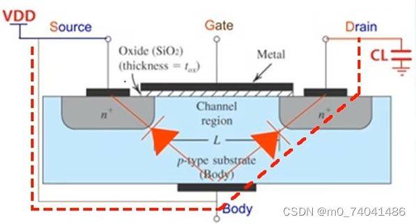
The vast majority of nmos sold on the market, b underline is usually connected to source pole s, so that the two electrodes have the same level of power and can avoid the transport of the threshold voltage caused by physical effects. Because b underline is linked to the source polar s, the diodes between b underline and s between source extremes are short-circuited, leaving only the diodes between b underline and leak polar d, and the bipolar tubes between s underline and leak polar d are shown below。
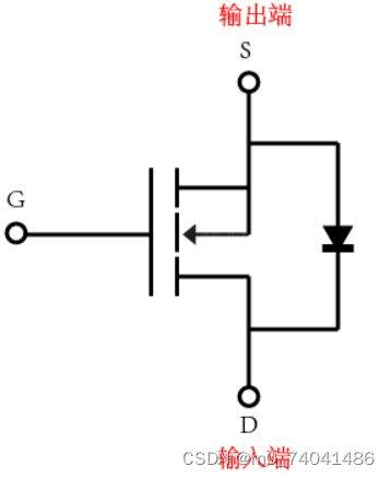
Watch the map. The arrows at source s are moving electronically
Parameters related to body diodes (leaking source diodes):
: diodes are moving towards currents
: diode positive voltage
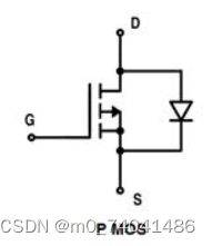
Map of pmos structure
The pmos structure is similar to the above nmos, with source s and leak d forming two diodes with bottom b, connecting source s and bottom b, with short circuits for diodes between source s and bottom b, except for diodes between leaking polar d and bottom b, i. E. Leaking polar d and source s
Application of pmos: electronic switches:
When one is high, two is low, the fence g is low, the source s is vcc high, pmos leads; and when one is low, two is high, both are high, pmos is unguided, and the direction of the bipolar tube is leak d points to source s, the cut-off state。
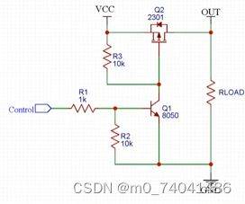
Control end low-altitude, triode non-conductor, source s and fence g connection high-altitude, pmos non-conductor; control end high-altitude, triode-conductor, fence g, source s high-altitude, pmos。
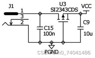
Leakproof electricity:
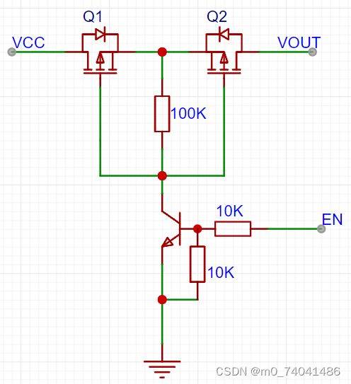
The source pole of q1 and the source pole of q2 are connected to the vcc because of the presence of the q1 body diode. Ping
En-end input low level, triode cut-off, q1 and q2 source and fence poles are high level, so q1 and q2 are unguided and vout is not exported. En-end input of high level, tripolar catheter, q1 and q2 grids to low level, source to high level, all to high level, vot output. The opposite direction of the q1 and q2 bodies allows the power to be completely shut down without leakage。
Application of nmos: for electronic switches:
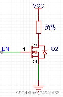
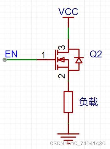
The en end is low level, and the nmos fence and source poles are low level and unguided. The en end is high, the fence is extremely high, the power is extremely low and the power is running。
Nmos load cannot be attached to low end. If the load is at a low end, en is low, the source is extremely low and unguided. En is high, but if the upper end of the general load is high, the fence and the source are high, so it is unguided. This must be self-propelled
If a single machine is used to control the mos tube, it is advisable to add a 100-om electrical resistance to the control foot。
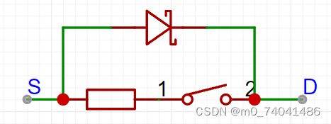
Nmos equivalence map:
Pmos equivalence map:
Mos tube parameters:
: leaking voltage between polar d and source s。
Equivalent electrical resistance between leaking polar d and source polar s. The smaller the better, the smaller the consumption, the smaller the heat。
Threshold threshold (door limit voltage) between grid g and source s。
: continuous leakage of polar currents。
Self-propelled circuit:
A self-activated cap (bst) is placed between the source pole s of the nmos tube and the leak pole d。
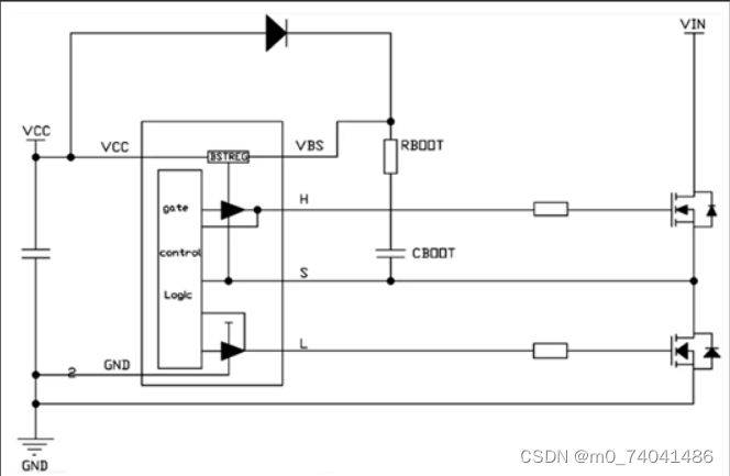
When h's low level, l's high level, up and down, down and down, bst's capacitating cboot charged through vcc, charged time for the down and down
; when h is high level, l is low level, the lower tube is shut down, and the upper voltage of the cboot is lifted because both ends of the capacitor cannot mutate. So the upper fence s voltage is greater than the source s voltage, which is wired, when the vboot voltage is discharged through rboot and internal circuits, and the discharge time is recorded
Bst capacitor selection
Use a better capacitor, preferably cog, or x7r at the most, not too big or too small (0. 1uf-1uf) to control the charge time. It is generally recommended that the bst capacitor be associated with a small electrical resistance (20 om) to reduce peak voltage. However, resistance to the general assembly's loss of some efficiency。
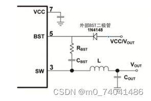
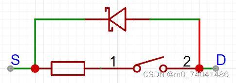
External bst diode efficiency improvement
An external bst diode (1n4148) can be used to increase efficiency when the ratio is high (greater than or equal to 0. 65). A power source between 2. 5 v and 5 v can be used to supply external bst diodes, as shown below。