01 trouble analysis and maintenance
Fault phenomena and preliminary analysis
Fault: when the power switch is pressed, the television sets, the red light comes on and then turns green in seconds, but there is no image on the screen, no sound, and it's completely dark。
Analysis and maintenance: in response to this failure, we know that the light is red to green, which indicates that both the sub-power and the main panel control systems are in normal working condition and that televisions have successfully entered open mode. But why is there no problem? There are two possible reasons: an anomaly in the main power component of the panel; and a malfunction in the signal and display system on the main plate。
Powerboard working principles and protection mechanisms
In order to explore further, we dismantled the television. We measured +5v voltage and +12v and +24v working voltage on the output plugin of the power plate. The measurements showed that the +5v voltage remained stable both on-board and on-board; while the +24v voltage was 0v on standby, it rose to +26v in an instant and then gradually fell to about 9. 5v; and, at the same time, the +12v voltage rose briefly to about +8v and then fell to about 3. 7v on-board. Based on these voltage changes, we can judge that the protective circuits have been activated and that further identification of the causes of protection is required。
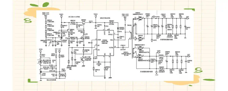
The power panel type used by the machine is kps+l180c3-01, and its integrated circuit combination programme includes fan7530, fsgm300, fsfr1700 and lm324, with the main output +5vsb, 24v and 12v voltages. The panels consist of three components: the secondary switch power, the pfc power factor correction circuit and the primary switch power. Among them, the secondary switch power is centred on fsgm300 and is responsible for generating key voltages such as +5vsb; the pfc circuit is centred on fan7530, calibrating and upgrading municipal electricity to 380v; and the primary switch power is centred on fsfr1700, generating 24v and 12v voltage as the main plate and other components. During the start-up, the sub-powers were first activated and powered for the control system, which was then given an opening instruction, and the pfc and main power circuits were activated, eventually bringing the entire unit into normal working condition。
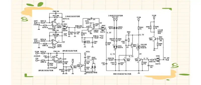
The machine has a pass-through, voltage-protected circuit centred on simulated transistor tubes q951 and q954, which closely monitor the switch circuit. The b pole of the transistor tube q954 is connected to the overpressure, overflow protection circuit, which, once overflow or overpressure failure has been detected, will inject a high level of power into the b pole of q954, prompting q954 and q951. This conductive state will reduce the switch to control the 1 foot voltage of the circuitine chord u902, which in turn will reduce the conductivity of the light chord u902. Eventually, the pfc-driven circuit uf901 and the vcc of the main power-driven circuit uw902 were reduced, resulting in the suspension of the power supply and the effective protection of the entire circuit. This is the working principle of overflow, overpressure protection tests。
Voltage measurements and protected circuit diagnosis
The first is the flow protection of primary power sources 24v and 12v, mainly through the a and b amplifiers of u956 (lm324). They test current-sampling resistance rw951 and rw952 at the end of the main power source 24v and 12v output circuits shown in figure 2 and deliver the detected voltage to 2 and 6 feet of the operating amplifier u956, respectively. Upon a flow failure, the 2 or 6 feet of u956 will be reduced (i. E., change in negative direction). At this point, the one or seven feet of the operating amplifier u956 will output a high level of power, which will be injected into the 10 footnotes of u956c by separating the diode d951. By magnifying u956c, output of high level of electricity from the eight feet, then sending high level of protection voltage via d952 to the simulated crystal line tube, thereby initiating the protection circuit and bringing the switch under control of the circuit to the standby state。
The second is over-pressure protection of the main power sources, 24v and 12v, which is largely achieved by the core of the steady-pressure tubes zd951, zd952. Zd951 and zd952 will be punctured in case of pressure failure and high-altitude protection voltage will be delivered to simulated crystal lines through the isolation of the diode d953 and will also be activated to allow the switch to take control of the circuit to remain on standby。
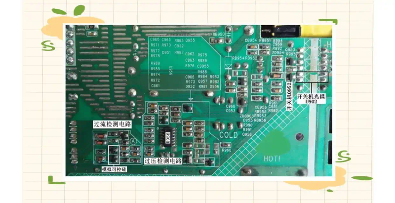
On the power plate, we can find the associated protected circuits, and by measuring the voltage of the protective poles, we can simulate the changes in the base pole voltage of the controlled silicon q954 to determine whether the protected circuits are activated. Since the base pole of q954 is connected to both overflow and overpressure detection circuits, in order to determine which of the detection circuits triggers protection, we need to measure when the engine is on. In the event that the positive polar voltage of the sid d752 remains constant at 0v at the start of the operation, this means that the excess protection circuit has not been activated. However, if the pressure protection of the polar voltage of the isolated diode d753 was measured, and it was found that the charge had risen to about 0. 5 v in an instant and then dropped to zero v, then it could be judged that the pressure protection circuit had been activated and had led to the occurrence of three non-facilities。
Maintenance steps and problem positioning
In order to further distinguish between the protection of fault protection caused by the problem of detecting circuit elements, or the excess of output voltage caused by the deterioration of circuit elements or damage to circuits from the main power source of the power plate, which triggers pressure protection circuits, we can treat them by decoupling。
1. Hypothetical load: first, remove the main power source's +24v and +12v output outlets xs953, xs955. Next, a 500-time electrical resistance was combined between the five and seven feet of xs955 to simulate a high-level electrical flat. In addition, a 24v motorcycle light bulb is attached between the 24v output end of xs955 and the six feet as a false load。
De-protection: short base pole-to-ground connections will be simulated to de-protect the q954 controlled silicon protected circuit。
The power is then powered by a power switch. Keep your hands close to the power switch. When the output voltage is detected to be excessive, the power should be cut quickly by the power switch to prevent further damage。
After electrostatic measurements, we found +24v voltage higher than 30v. This suggests that the driver may have caused protection by the deterioration of the stable voltage circuit element of the main power source or damage to the circuit, resulting in an excess of the output voltage, thereby triggering the voltage protection circuit。
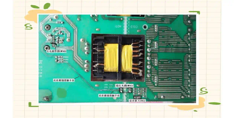
Based on maintenance experience, we suspect that the error amplifiers of the steady-pressure circuits and the steady-pressure rays may have been damaged. However, after the replacement of these elements, the failure persisted. As a result, steady voltage circuits were further carefully measured and inspected. The results show that the four feet of the light-link uw903 to the two feet of the main power source, uw902, and the three feet of the light-link uw903, to the six feet of the main power source, uw902, have a layer of green hair. After scraping out the green hair, we found signs of corrosion. In addition, resistance measurements indicate poor exposure to copper platinum, which leads to the main power source thick membranes 2 and 6. In order to solve this problem, we were able to successfully eliminate the malfunctions by connecting the circuits between the two directly with the line。