Contents
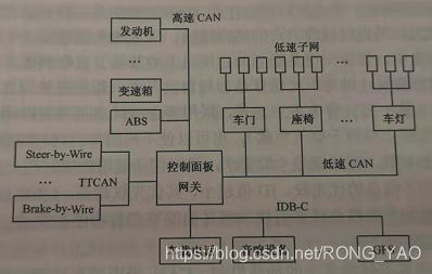
Application of the can bus to the network of vehicles ii. Application of the can bus to the vehicle the most advanced information is sent without interference. The x-by-wire system: as the electronic technology of vehicles continues to develop and the car system is integrated, people can drive cars by electronic means without the need for traditional mechanical transmission of control signals. This electronic means (x-by-wire). “by-wire” may be called electronic wire control, while “x” represents systems in cars. E. G., line control turn (steering-by-wire), line control movement (blake-by-wire). The x-by-wire system, which requires certain behaviour during a communication service, even when the bus load is maximum, the sending of security-related information must be guaranteed, and when the message is sent with maximum precision, it must determine the likely time point. Time-trigger agreement ttcan based on can bus: its communication is done through a time-oriented periodic dispatch of reference messages. Ttcan's advantage: it is also possible to send an incident trigger agreement within a certain window of arbitration time, and these windows of time that give rise to normal arbitration allow spontaneous messages to be sent。
Can-based car network system
Characteristics of can bus
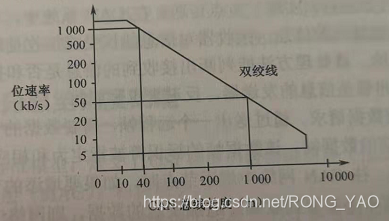
Maximum transmission distance of the can bus in relation to its bitrate
Basic features of can
1. Bus access is based on a multi-mainstream approach based on priority。
Non-destructive mechanisms for arbitration based on competition over lines。
3. Multi-node transmission using acceptance rate wave pair frames
4. Supporting remote data requests
A remote data frame sent by the node, which can request another node to send itself the corresponding data frame, the expression of which is designated to be the same as that of the corresponding remote frame。
5. Flexible configuration
When adding nodes to the can network, if the added nodes are not senders of any data frame or if the nodes do not need to receive any additional data sent, none of the nodes in the network will be subject to any soft and hardware adjustments。
6 data consistency across the system
Making a frame acceptable to both all nodes at the same time and not to any nodes at the same time is perfectly possible within the can network. The system thus has a consistent feature, which is obtained using multi-point transmission principles and failure management。
7. Error detection and error notification。
Can bus contains several measures to detect errors
8. Frames damaged by failure of arbitration or failure during transmission can be retransmitted
9. Capable of distinguishing between temporary and permanent malfunctions of nodes and automatically breaking down the nodes points
The can node can distinguish between short-term interference and permanent failure, and the failure node may be broken, which means that it is disconnected from the logical connection to the bus (i. E., it is not capable of sending frame or accepting frame)。
Normally, a can node must be in an error-activated, wrong-approved or offline state。
Iii. Structure and functions of can
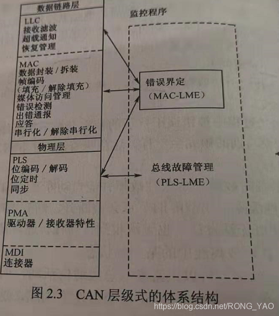
Can defines an osi model following iso/osi standard model
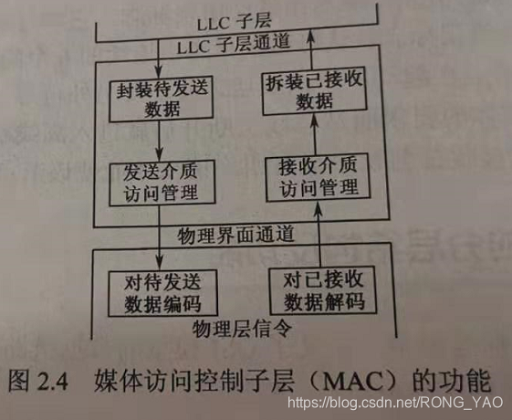
Following the osi reference model, can's system structure reflects two layers corresponding to the osi reference model: the physical layer, the data link layer. In accordance with iso 8802-3 (lan standard) and iso 8802-2, the data link layers are further divided into the logical link control layer (llc) and the medium access control (mac); the physical layer is further divided into pls, pma and mdi. Fault definition: a management entity operated by the mac sub-layer, called the “default definition entity (fce),” which is defined as a self-leaving mechanism that distinguishes between short-term interference and permanent failure. The physical layer is an entity monitoring that detects and manages physical media malfunctions (short circuits or interruptions, bus failure management). Mac (multimedia access control sublayer) is the core layer, which can be divided into two parts of a fully independent operation。
The physical layer achieves the ecu-connected circuit. The total number of ecus depends on the power load of the bus, and can is able to use a variety of physical media such as double winch, fibre-optic. Two winch lines are most commonly used, with signals transmitted by differential voltage, and two signal lines are known as can h and can l. At static times around 2. 5 v, the state is either logical or implicit. Use can h over can l to express logic 0 and call it explicit. The normal voltage value at this time is can h=3. 5v can l=1. 5v。
Iv. Context of can
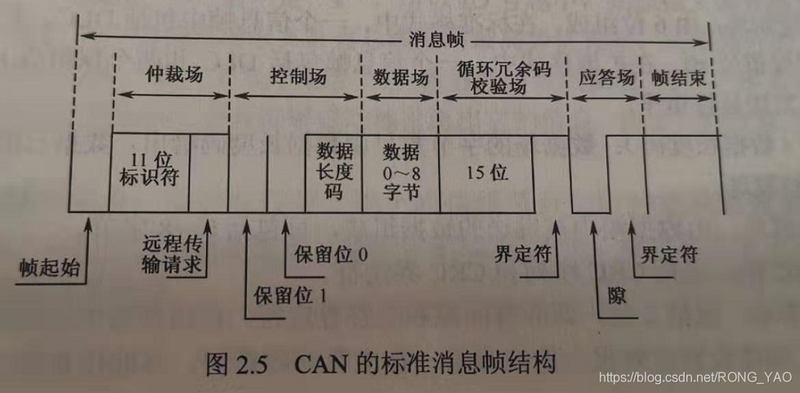
1. Standard format for can message frames (can 2. 0a message frames)
Can has two types of message frames, which are different in the length of id, can 2. 0a, standard format for can 2. 0a, 11-bit identifiers.
The can2. 0a-based network can only receive information in format from the following maps。
2. Extended message frame (can2. 0b information frame format)
29-bit identifiers, the first 11, the same as the can 2. 0a message frame, and the next 18 dedicated tags can 2. 0b
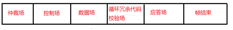
4. 1. Can four message frames by purpose
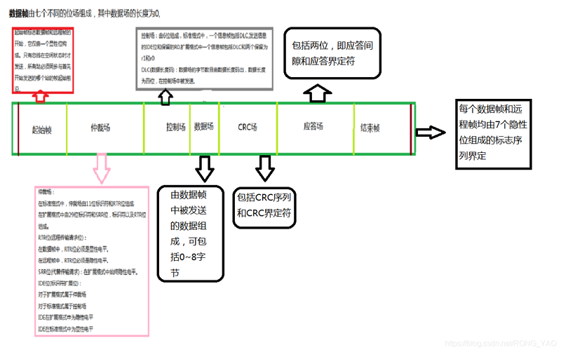
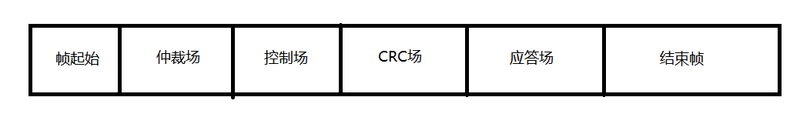
Initial frame: marks the beginning of the long-range frame and the data frame, which consists of only one dominant position and is only allowed to start when the bus is idle
Court of arbitration: standard format: consisting of 11-bit identifiers and rtr (requirements for remote transmission)
Extension format: 29 identifiers and srr bits (in lieu of transmission request), identifiers and rtr bits。
Rtr bits: in the data frame, the rtr bits must be visible and in the remote frame they must be invisible。
Srr bits: remain hidden in the extension format。
Ide bits: ide bits belong to the arbitral tribunal in the extended format, when ide bits are hidden. For a control field in a standard format, the ide position is visible。
Control field: 6-bit composition standard format: a frame of information includes dlc, send an ide displaying level and keep r0 in
Extension format: a frame of information including dlc and two reserved r1 and r0 must send a visible level
Dlc (data length code): the number of bytes in the data field is given by the data length code, the data length code is 4 bit and is sent in the control field。
Data field: consisting of data sent in the data frame, which may include 0-8 bytes
Crc field: includes the crc sequence and crc identifier
Response site: includes two (response gaps and response definition) and two implicit slots are sent from the station at the response site. A good receiver receives a valid message, transmits this information to the sender in the form of a prominent message during the response gap, receives all stations that match the rcr sequence, reports the implicit writing of the explicit position into the sender in the response gap, and defines the second place in the response range, which must be hidden。
End of frame: each data frame and remote frame is defined by a series of signs consisting of seven hidden places。
Node to receive data can be sent by sending a remote frame requesting source node
There's no data field in the remote frame. It's a hidden level of rtr
The frame of error consists of both the wrong mark and the wrong definition。
When an error is detected on the bus at the receiving node, the error sign will be automatically issued, consisting of six consecutive prominent positions。
The other nodes detect the wrong sign of activity and send the wrong endorsement sign, consisting of six consecutive hidden positions。
There may be time differences in the receipt error markers for each node, so that the physical error mark on the bus may consist of 6-12 hidden places。
The error definitionator consists of eight hidden electroplasms, which are monitored by the bus at each can node after the error sign has occurred until the jump of a visible electroplasm is detected. Up to this point, you have completed the sending of the wrong mark and you have started sending eight definitional characters for hidden electrons。
The overload frame consists of two bits of overload sign and overload definer。
Two types of overload conditions that trigger the transmission of overload marks:
1. The internal conditions of the receiver that requires the delay in sending the next data frame or remote frame。
2. Visibility is detected at the first and second parts of the interval, with the overload sign consisting of six femininities, and the overload definer consisting of eight consecutive hidden places。
4. 2. Non-destructive-level arbitration
Related boven1