Purpose of the experiment
1. Understanding the role and status of antennas, and understanding the definition of comprehensible and receiving antenna electrical parameters
2. Deep understanding of the relationship between electromagnetic radiation and antennas and mastering performance indicators describing the receiving antenna
3. Knowledge of the fundamentals of understanding electromagnetic radiation。
4. Three conditions for mastery of the fres transmission formula and maximum capacity of the receiver。
To understand the relationship between the launch antenna and the receiving antenna and what is required as the receiving antenna。
Ii. The experimental rationale
The electromagnetic wave radiation is the interaction between the electric field and the magnetic field, the resulting fluctuations, and the transmission of radiation to afar. Electromagnetic energy is removed from the grip of wave sources and the phenomenon of spatial transmission is called electromagnetic radiation. The radiation of electromagnetic waves is an objective physical phenomenon, which is extremely important for wireless communications, navigation and radar and needs to be fully exploited; in some electronic systems, when the radiation of electromagnetic waves or radio leaks can affect the normal work of other equipment or systems, electromagnetic radiation becomes a harmful electromagnetic interference and the necessary restrictions are required. Antenna radiation is electromagnetic waves, which receive, but it is not the electromagnetic waves that are sent into the antenna by the transmitter through the feedback, nor can the receiving antennas send the electromagnetic field waves directly through the feed to the receiver, where the energy conversion is required. In addition to being effective in radiation or receiving electromagnetic waves, antennas complete the conversion of high frequency currents to the same frequency as electromagnetic waves or the conversion of high frequency currents to the same frequency. So the antenna is an energy converter。
Electromagnetic wave radiation shall be produced under the following conditions:
1. There shall be a variable source, which may be a variable charge source, a variable current source or a variable electromagnetic field. In order to effectively produce electromagnetic radiation, the frequency of the temporal variant should be sufficiently high, and, more precisely, the radiation system's size energy and the electromagnetic wavelength ratio are likely to produce significant radiation effects。
Wave power circuits shall be open. The way the power circuits are structured has a significant impact on radiation strength and weakness. Closed circuit structures, such as convulsive cavities, do not produce radiation. The more open the power circuit, the greater the radiation。
The radiation of an electromagnetic wave can be formed when the steering line contains a transient field, and the radiation capacity is related to the length and shape of the steering line. If the direction is as a figure, the distance of the two lines is very close, and the sensory electric motion generated by the two lines can almost be offset and the radiation is therefore very weak. If the two lines are open, the radiation is stronger because the current direction of the two lines is the same, and the sensor electric motion direction of the two lines is the same. When the length of the conductorl is much less than the wavelength, the current of the conductor is small and the radiation is very weak。
The graph below shows the process by which a parallel two-way transmission line from high frequency open roads is given to an antenna. At the beginning, there was a wave distribution of the electric field between parallel two-conductor transmission lines, and the radiation of the electromagnetic waves could occur when there was a flow of transient currents on the conductor, and the radiation capacity was related to the length and shape of the conductor。
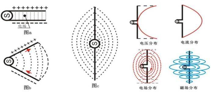
Figure 1
1. As shown in figure a, on two parallel steering lines, the current direction is the opposite and the distance between the lines is much smaller than the wavelength, and the electromagnetic fields they stimulate are offset by the opposite of most of the space outside the two lines。
2. As shown in figure b, the end of the two lines is gradually opened, so that in some directions the electric field is spread in the surrounding space, the electromagnetic field generated by the two lines cannot be offset and the radiation will gradually increase。
3. As shown in figure c, when the two lines are fully open, the electric currents on the open arms are in the same direction, and the electromagnetic fields they stimulate in the surrounding space are offset only in a certain direction by a symmetrical relationship, and in most directions they overlap and increase radiation significantly。
4. When the length of the lead line is much smaller than the length of the wavelength, the radiation is very weak; when the length of the lead line is increased to a level close to the wavelength, the currents on the lead line will be significantly increased and will result in stronger radiation. This structure is known as the open structure. An antenna with a parallel two-conductor transmission line open at the end of the road is the usual symmetrical tremor antenna, the simplest antenna。
Best reception conditions:
1. Matches an antenna with the respective feeder resistance
2. Polarization matching
3. Maximum radiation orientation of the receiving and receiving antennas to the terminal load
Felice transfer formula
To receive power
For the purpose of launching and receiving gains from antennas
Launch power, r for transmission distance。
Iii. Context of the experience
1. To build an experimental platform to master the fres transmission formula and the three conditions of maximum reception power。
Studying the relationship between radiation and antenna shape and understanding the relationship between the launch antenna and the receiving antenna。
3. Hand-held microbands for the eight log antenna in search of the maximum direction and zero radiation direction of the launch antenna and the rear valve level。
4. Deep understanding of the relationship between electromagnetic radiation and antennas。
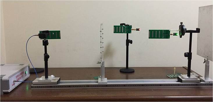
Figure 2
Iv. The experimental steps
1) to connect the cable rf with the polarized antenna vent by sma to the polarized antenna。
2) installation of the octak antenna on the rotary rack, vertically placed and moving to a distance of 80 to 90 cm from the launch antenna。
3) hand-held microbands to receive the eight log antenna in the direction of the coming wave, moving the receiving antenna around the launch antenna on the h side to measure the light distance of the led light, paying particular attention to the light distance between the side and the rear。
4) hand-held microbands to receive the eight log antenna in the direction of the coming wave, moving the receiving antenna around the launch antenna on the e side to measure the light distance of the led light, paying particular attention to the light distance between the side and the rear。
5) comparison of e and h petal width。
6) redo the above experiment using different colours led。
V. Notes
1. When pressing the button, if there is no power output, the launch shall immediately cease, check whether the radio frequency cable head is strongly connected to the instrument's interface, check whether the sma head of the small radio frequency cable is strongly connected to the input port of the antenna, and export a 10db decayor to prevent micro-alteration when measured by microbalm. Prevention of the burning of microwave amplifiers by airborne work。
2. Minimize the time to press the button so as not to affect the accuracy of the tests of other groups。
3. Tests are conducted in such a way as to avoid the movement of persons to avoid the results of human reflections。