Technical brief:
The patent proposes improvements in the application of pallet mass placement of glass, automatic transmission by transmission agencies, uvled light sources and photo-remedial structures for the complex, inefficient, high-cost mask panels and short photolife of traditional 3d curve glass exposure machines. Co-examination of glass through the integration of palettes into mask panels and refilling prisms, increasing efficiency and addressing the loss of ink due to low light on edges, and replacing mercury lamps with low-environmentally friendly uvled light sources。
Keywords: 3d curve glass exposure machine, uvled patch
This practical new type involves 3d curved glass treatment techniques, in particular a 3d curved glass exposure machine。
Background technology:
In the 3d panel area, the printing process, in addition to the traditional filament and migration, is the laser etching and exposure ink. Exposure machines are one of the core equipment in the exposure ink process。
Existing exposure machines are basically projective. The projection exposure is the method of using optical projection imaging to project the graphics of the mask through the projection mirror onto a panel coated with a sense of light. The mask graphics are a few centimetres away from the sheet, and the mask graphics are projected to the 3d sheet and repeated through step-by-step exposure of multiple sheet surfaces。
The projectors currently in use in the 3d panel area are the following:
1. The projectors are complex in structure, demanding the precision of the sports institutions, and are difficult to manufacture and expensive, making it difficult for domestic equipment manufacturers to manufacture and rely mainly on imports。
2. The projector will only be able to complete the processing of two sheet glass at a time and produce inefficiently。
3 the mask panels used by the existing projector need to be filtrated and constructed at high cost and long duration。
The projector generally uses mercury light sources as a source of exposure, which are short-lived, high-power and ozone-producing and polluting。
As a result, existing technologies need to be improved and enhanced。
Technical realization elements:
In view of the deficiencies of the existing technology, the purpose of this practical novelty is to provide a 3d curved glass exposure machine that will increase the efficiency of 3d glass exposure。
To that end, the following technical programmes have been adopted:
A 3d curvature glass exposure machine, which includes: an exposed machine and trays used for the placement of several 3d curvature glass; the said exposure machine has an exposure room, a conveyor and a first driver for the drive of the said conveyor tray; the said first driver is connected to the transmitter; the said exposure chamber has an exposure source for the exposure of the 3d curvature glass; the said source is located below the exposure room; and the said exposure source is located above the exposure room。
In the 3d curved glass exposure machine, the tray in question consists of the tray base, which contains a number of dents for the 3d curved glass and a mask plate。
In the 3d curved glass exposure machine described, there are a number of patches on the tray base used to reflect the light from the exposure source to the perimeter of the 3d curved glass。
In the 3d curvature glass exposure machine described, the arctic slope described is the side of a prism reflecting block。
In the 3d curved glass exposure machine, there is a plume-reflection column around each of the grooves。
Of the 3d curved glass exposure machines described, 15 were dents。
Among the 3d curved glass exposure machines described, the transmission apparatus in question consists of a number of transmission axes set in parallel. The first driver in question consists of a conveyor belt and a drive engine used to rotate the transmission axis; the driver in question is connected to the transmission axis through the transfer belt。
In the 3d curved glass exposure machine described above, there are test modules on the body of the said exposure machine to detect whether the exposed area is subject to exposure。
In the 3d curved glass exposure machine described, the exposure source included several parallel uv led lamps。
Compared to the available technology, this practical new type of 3d curved glass exposure machine includes: the body of exposure and the tray used to place several 3d curved glass; the body of exposure with the exposed room, the transmitter and the first driver used to drive the delivery tray of the transmission body; the first driver referred to; the provider connected to the transmitter; the room of exposure with an exposure source used to expose the sensory ink on the 3d curved glass, which is located below the exposure room; and the source of exposure described is located above the exposure room. This practical novel place several 3d curved glass via trays, which are automatically sent into the exposed room by the transmitter, are automatically exposed by the exposed light source and have a large number of 3d curved glass that can be exposed at a time, greatly increasing the efficiency of work。
Annex figure description
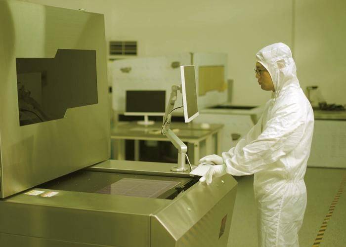
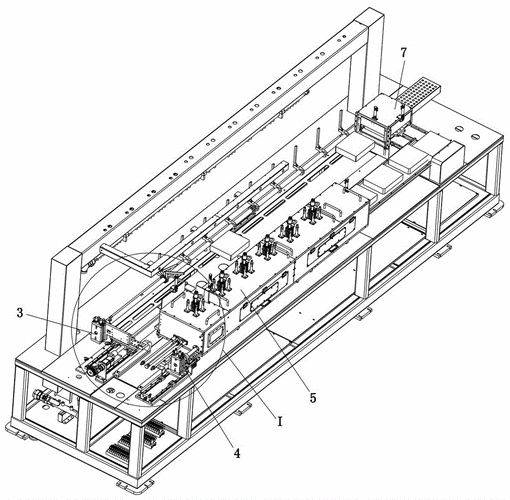
Figure 1 provides a snapshot of the 3d curved glass exposure machine available for this practical novel。
Figure 2 is a practical, new version of the 3d curved glass exposure machine with a chart of the tray structure。
Figure 3 is a practical, new version of the 3d curved glass exposure machine for palette patches。
Implementation modalities
In view of the shortcomings of the existing technology, the purpose of this practical novelty is to provide a 3d curvature glass exposure machine, with a view to making the purpose, technical options and effects of this novelty clearer and clearer. It should be understood that the specific implementation examples described here are intended to explain this new practical development and not to qualify it。
See figure 1 and figure 2, this practical new type of 3d curvature glass 100 exposures, including 41 and 42 of the exposed body, with a number of 3d curvature glass placed in 42 per tray. The exposed body 41 is equipped with an exposure room, a transmitter (not marked in the chart), a first driver (not marked in the chart) and a control cabinet 414。
The first driver in question is connected to the transmitter, the first driver in question is used to drive the delivery tray of the transmitter in question, 42, the exposed light source in the exposed room 44 is located at the lower end of the 3d curved glass, 43, which is located at the upper end of the exposed room。
This practical novel completed the image transfer process by placing in tray 42 a number of 3d curved glass 100 panels, and sending the 42 trays automatically into exposure room 44 by the transmitter, placing the 3d curved glass 100 panels from exposed light source 43, exposing the ink of the 3d curved glass 100, exposing multiple 3d curved glass 100s at a time and automating the operation, significantly increasing the efficiency of work and reducing human costs。
See also figure 3, in this practical new type of 3d curved glass 100 exposure machine, the tray in question includes 421 the tray capital, with a number of dents for 100 for 3d curved glass in 421 and a mask plate in 423 in 423. The image transfer was completed by exposure of the 3d curved glass 100 sense ink by irradiating tray 42 from the exposed light source。
At the time of implementation, the mask 423 and 3d curved glass 100 used the same materials, reducing the cost of the mask 423. The above-mentioned exposure sources43 include several parallel uv led lamps, which are low-efficiency, long-lived and non-polluted. In this case, the exposure source was 43 at 180 - 220 mw/cm2 and 650 - 780 jm/cm2。
The number of grooves in question is 15, i. E. 15 pieces of work per tray can be placed on 42 and 15 products can be exposed at a time, which greatly increases the efficiency of work。
Since the uv led light discharges parallel light vertically to the centre of the 100-bed 3d curved glass, the surroundings of the 3d sheet glass are all curved, with less luminous than the centre, which can easily cause the surrounding ink to fall due to insufficient light. This practical novel introduces a number of light-reflection slopes of 422 on the tray base 421 that reflect the perimeter of the exposed light source 43 out of the 3d curved glass, by which the vertical light is reflected on the perimeter of the 3d lid glass by 422 to increase the exposure of the perimeter of the 3d lid glass to avoid the loss of the surrounding ink due to insufficient light。
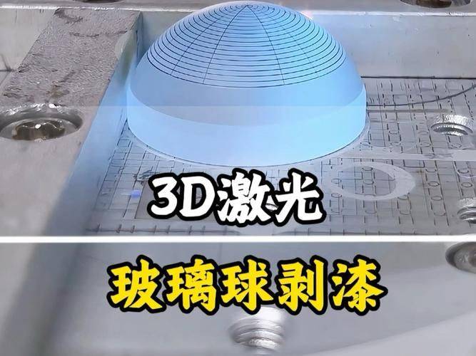
In a better case, 422 of the said recharge slopes is the side of a prism reflecting block, such as a trilinary reflecting block, so that a prism reflecting block can provide a simultaneous light slope of 422 for two adjacent dents. For practical implementation, the reflecting face of the tri prism reflector block is the mirror and the non-reflective reflector is the rough face, so that the prism reflector block is reliably coupled with tray 42. More appropriately, the surroundings of the plume are each equipped with a plume reflecting block, which allows for a greater light on each side of the 100-percent side of the 3d curved glass, and a plume reflecting block adjacent to the two puddles, which saves material while reaching the power of light recharge。
Please continue to refer to figure 1, which includes transmission axis 431, which consists of several parallel settings, and the first driver, which consists of the transmission belt and the drive engine used to drive transmission axis 431, which is used to rotate tray 42, which is linked to transmission axis 431, through the transmission belt (unspecified in the chart). Several parallel-set transmission axes 431 form transmission lines, which can be belts, which are rotated by transfer belt-led transmission axis 431 when the driver works. In this implementation example, the above-mentioned first-driving agency controls transmission axis 431 at a speed of 2. 4 m/s, which greatly increases the efficiency of the operation if the adjacent tray 42 centre space is 0. 6 m with four pallets per minute。
For a better understanding of this practical new type of 3d curved glass 100 exposure machine, the following results, figures 1 to 3, elaborate on this practical new type of 3d glass 100 exposure machine:
The coating glass (e. G., cell phone plaster glass) that is sprayed with light ink is pre-rigged, and the glass pen is put into the chute of 42 of the tray, which is then placed on the sheet with glass pen into the mask panel 423, and then the tray 42 is placed on the delivery line formed by the transmission axis 431, which rotates at 431 zidly, making the tray 42 at speed, and entering the exposure chamber 44 where the detection module is detected and exposed to the exposure sheet. During exposure, the transmission axis 431 was rotated at a flat rate, sending the tray 42 into the next process。
In this example, 15 3d curved glass of less than 7 inches could be placed on a tray of 42 at a time, which would result in the exposure of 15 products. The release of 15*4 = 60 3d curvature glass was completed with the production of trays 42 moving at a rate of 2. 4 m/s at a distance of 0. 6 m from the centre of the adjacent tray 42, with four pallets per minute. Also, the speed of the driver, the power of the exposed light source, etc., can be set by operating panel 401。
In the light of the above, this practical new technology has the following beneficial effects compared to existing technologies:
High capacity and efficiency. Fifteen products are placed on each tray, with multiple trays running continuously, with 60 products exposed per minute。
2. Exposure, simple equipment structure, low precision requirements for sports institutions and low manufacturing costs。
3. Use of reflector light to increase perceiving in the periphery of the lid glass, using fixed patches on the pallet, and without increasing the area of light sources and luminance, effectively solves the problem of the loss of periphery ink due to the insufficiency of light。
4. The use of the same materials as glass sheeting is used to make mask panels, which are low-cost。
5. Use of uvled light source, long life, low power, ozone-free, green。
It is understandable that, for ordinary technicians in this field, replacements or changes can be made on the basis of this practical new technological approach and its design of inventions, all of which should fall within the protection of the claims attached to this practical new type of technology。