(3) double-clicked water turbines (banki turbine, cross-flow turbine), after which the water flowes out of the nozzle, enters the rotor centre from the outer circle of the wheel by a routing to the blade for a first energy exchange, and from the rotor through a routing to the blade for a second energy exchange, figure 3 (c). The surface range of 10-1500m is simple, inefficient, less productive and less applied。
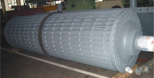
Figure 8 - double-click water turbines
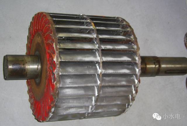
Figure 9 - double-click tankers
(figure 8, figure 9 comes from the small hydropower qq group)
Reaction turbine
Unlike shock-type water turbines, countervailing water turbines take advantage of both current power and kinetic energy, with currents filled with the entire rotation space, changing the speed and direction of the rotor blades under the constraints of the rotor blades, thus being counterproductive and driving the wheel rotation. Most of the kinetic and dynamic energy flowing through the water turbines is converted into a mechanical rotational function. Responsive water turbines can be divided into axle flow, mixed flow, tilt flow and flow。
(1) axial-flow turbine
Axle-stream water turbines are rotated like fan blades and operate in similar ways to common wind engines. The current flows from the water turbines in a horizontal direction to the centre (the run-in) and then to a downward direction to drive the rotor blades for work, which is called the axle-stream water turbines because the flow that drives the rotor blades parallels the direction of the rotor axis. Figure 10 shows the flow patterns of axle currents。
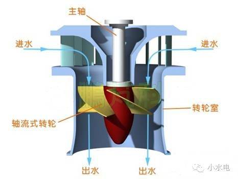
Figure 10 - axis-stream water flow map
Axle-stream water turbines are installed in the rotor room at the top end of the rotor's ring, with a top cap at the upper end of the ring, with a steering bearing in the centre of the cap, which supports the wheel; in the lower part of the cap there are seals to prevent high pressure water from entering the equipment space above the top of the cap through the axis; in the leaves are installed between the bottom ring and the top, and on the top is a component of the water conductor such as a control ring and a relay; and under the rotor room there is a connection to the tail pipe. The flow of water goes through the steering leaves into the rotor room and drives the wheel to function and then discharges from the tailings, with a light blue arrow line indicating the direction of the flow, as shown in figure 11。
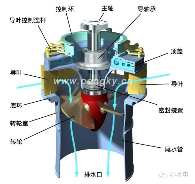
Figure 11 - wheels and water conductors of axle currents
Axle current water turbines are divided into propeller turbine and kaplan turbine。
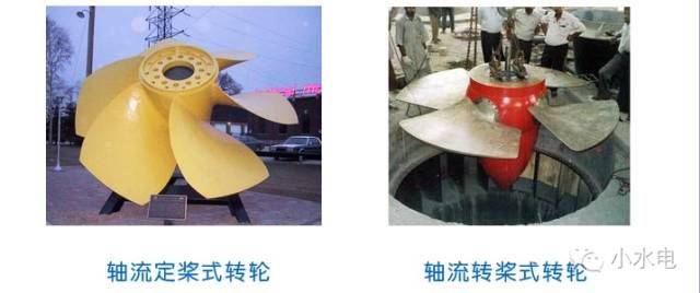
Figure 12 - axis-stream tankers (photo from the network)
The blades of the axle-flowing oars are fixed on the rotor body, the angle of the foliage cannot be changed in operation, the efficiency curve is steeper, and apply to power stations with small load changes or with adjustments to the number of stations operated by the unit. Advantages: simple structure, lower cost. Shortcomings: a sharp decline in efficiency when de-designing. Depending on their characteristics, they are generally used for less productive hydropower plants, lower water and less variable water。
The axle-turner water turbine was invented by austrian engineer kaplan in 1920 and is also known as the kaplan water turbine. The rotor blades are generally operated by oil pressure relays installed in the rotor's body and can be rotated accordingly by changes in the water head and load in order to maintain optimal co-operation between the directional and lobe turns, thereby increasing the average efficiency, which has exceeded 94 per cent. However, such water turbines require an agency to operate the shifting of blades, which is more complex and expensive, and is generally used for large- and medium-sized hydropower plants with a large variation in capacity。
(2) mixed water turbines (francis turbine, mixed flow turbine)
Streams of mixed-stream water turbines flow to the centre from the peripheries of the water turbines horizontally into the rotor (routing into the centre) and then to the export in the lower direction, into the inner axis of the rotor the wheel is promoted when the leaf is passed in the direction, and when the leaf is passed down. This means that water flows through the blades both in diameter and axis, and is therefore referred to as mixed water turbines, also known as wind currents。
The hybrid water turbine is one of the counter-attacked water turbines, which was invented by united states engineer francis in 1849 and also known as the francis water turbine. Figure 13 shows the flow patterns of mixed-flow tankers。
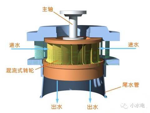
Figure 13 - flow patterns of mixed-flow tankers
The condensed, efficient and broad surface-based mix of water turbines is one of the types currently widely used worldwide。
The main components of mixed-stream water turbines include snail shells, rings, water conductors, caps, rotors, main axes, bearings, bottom rings, tailings, etc., as shown in figure 14 (the rings have been omitted to make the picture clear and simple). The light blue arrow line in the figure represents the flow of water through the water turbine, which enters the water turbine from the entrance to the snail shell, enters the wheel through the directional leaves forming a circular flow to the centre, and pushes the rotation to operate and is discharged from the lower tailpipe。
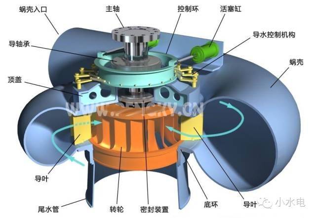
Figure 14 -- mixed-stream water turbine structure figure
The hybrid water turbine is applied to the surface from 20 m to 700 m, is simple, stable and efficient, but it is generally used in the middle water (50 m to 400 m). From dozens of kilowatts to hundreds of thousands. Currently, the maximum capacity of such tankers exceeds 700,000 kilowatts. Our single-capacity 700 mw hybrid aircraft are operational in the three isthmus。
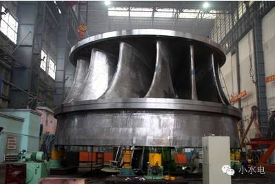
Figure 15 - mixed-stream water turbine rotors (700 mw units)
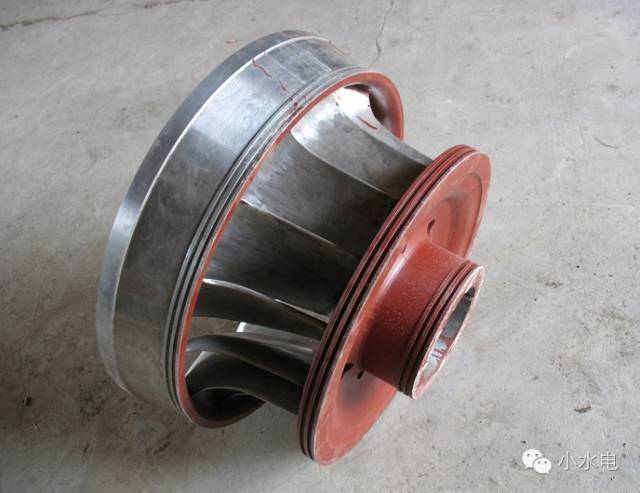
Figure 16 - mixed-stream water turbine rotors (photo from the web)
(3) tiagonal flow turbine, inclined flow turbine
The oscillating water turbines are somewhat like axle-streamed water turbines, except that the currents through leaves are tilted in the direction of the axle, they are the variants of axle-stream water turbines with small current energy loss and adjust to the larger surface range by regulating the angle of the blades. Slash-stream water turbines are currently less used because of the complexity and high cost of manufacturing processes. Figure 17 shows the direction of the water flow of the tilt-streamer。
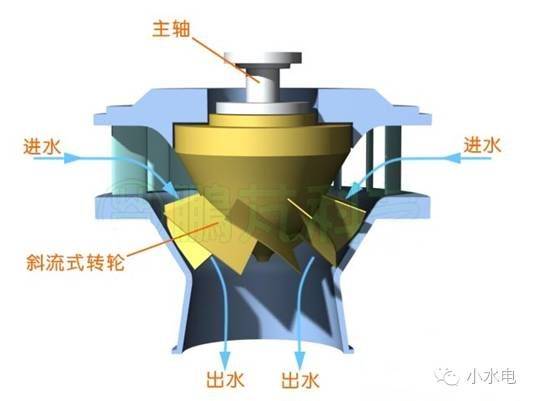
Figure 17 - slash-stream water flow map
(4) transcontinental water turbine (straight-flow turbine)
Transcontinental water turbines are basically the same as axle water turbines, but the rotor is horizontal or slightly tilted, and the current flows in and out of the direction of the water turbine axis. Figure 18 shows the flow patterns of the trans-stream water turbines。
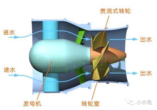
Figure 18 - trend water flow diagram
Transcontinental water turbines are mainly operated in four forms: shaft-extension type tabular turbine, pit-type turbine, bulb turbine, rim-generator turbine, and are currently used very rarely due to the high requirements of the process of construction of a full-stream water turbine。
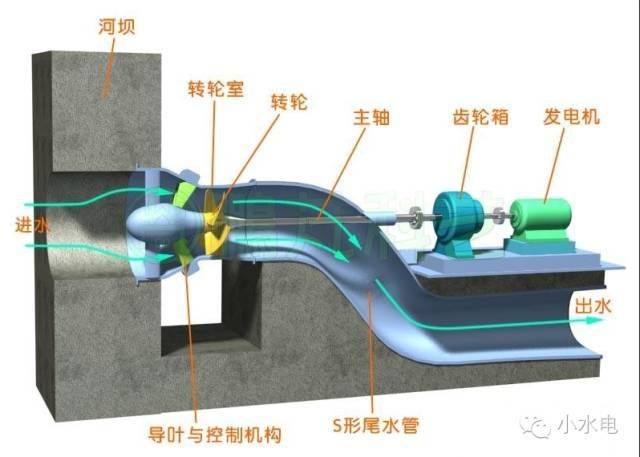
Figure 19 - chart of axial flow-through-streaming water turbine generator sets
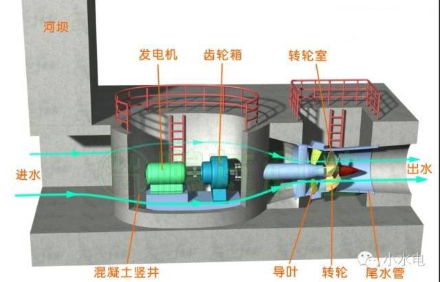
Figure 20 - scheduling of vertical water tanker generators
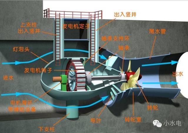
Figure 21 - chart of the current water tanker generator set
Reversible water turbines (pump-turbine)
Reversible water turbines, also called pumps, are a hydraulic machine that can be used both as turbines and as pumps. In theory, mixed water turbines, axle-stream water turbines, and tilt-stream water turbines can all be reversible and are in fact designed to function efficiently in two operational states。
Iv. Main types of water turbines and applicable headwaters
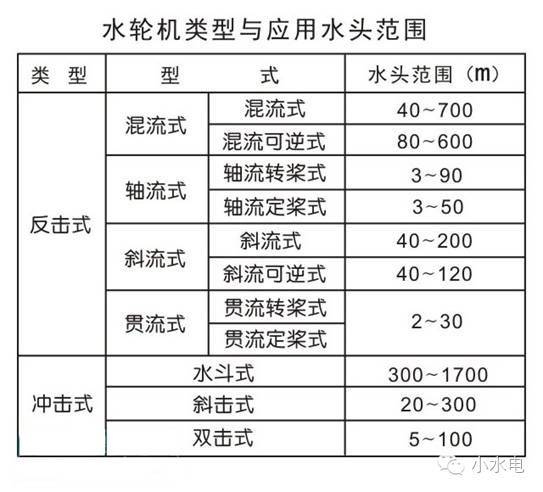
The following table shows the main types of water turbines and the applicable surface range (with different data, for reference purposes only)。