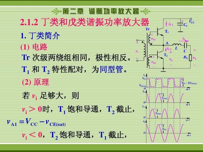
The working conditions of the transistor transistor are very closely related to the frequency, which can normally be divided as follows: the low frequency area (f0. 5 f β) is 0. 5 f f 0. 2 ft high frequency (hf) area (0. 2 ft) with the ft β fb (beta) transistor working in the low frequency area, without regard to the effects of the electrical resistance in its equivalent circuits and the passage time of the current. The calculation of the analysis of the medium-frequency area takes into account the function of each capacitation of the transistor. In the hf area, further consideration needs to be given to the role of electrodes in wires. As a result, rigorous analysis and computation in the medium- and high-frequency areas is difficult. The book will explain the operation of transistor high frequency amplifiers from low-frequency areas. Return fβ - cut-off frequency ft - quality-frequency learning points this section conclusion i: seeking to minimize the dissipation power of collector poles at pc will naturally increase the efficiency of collector poles. In this way, the transistor exchange output power will increase when given p=. Pi — input signal power 2 — efficiency and power efficiency method basic circuit for hf power amplifiers continue to end the page + vb - - + vb ib ib ic lvc vc vc vcc vbb + - + + + + + = = ω ω i i i c i i + + 。 = = = = = = = = = 高频 = = = + = = + + = = + = = = + = = = 。 = + = = 。 = + = 。 = = = = 高频 + + 。 。 = + + 。 = + = 。 = + = = + + 。 。 。 。 。 = + + + 。 = 。 。 。 。 = 。 。 。 2 θc 5. 2 the working method of the cosonator is that t/2 π is required to achieve efficiency if the wave shape of vc and ic of the transistor is shown (note that vc and ic are opposite in the co-radiation circuit). High frequency power amplifiers' basic circuits continue to complete the page + vb - + output + - vb ie ib ic c l vc p vcc vbb + - ic ωt ic, vc θc 2 θ t/2 pc = ic vc transistor in c state, so ic can only pass at vc's lowest, so pc is the smallest and most efficient in c working condition. 5. 2 the working method of the resonance power amplifier i. The condition for efficiency is 2 gillc, which is the circulation angle of the total electrode current over a one-week period, with a semi-circle angle (also known as the cut-off angle), which is referred to in this teaching material. Continues with the values for ovb ic, vc θc 2θc t/2π3 and for the calculation of ovb ic vb-vbb by the end of this page for 2θc 通vbz+vbb. Vbz vbm transfer feature curve input signal is a communication sine wavevb. 2 θc ic ωt o only produces ic in this area that's double angular c. 5. 2 the working method of the resonance amplifier i. The conditions required to achieve efficiency continue. At the end of this page, o ωt ic, vc θc 2θc t/2 π3, the calculation of o vb ic vb - vbb 2θc vbz vbm transfer curve 2 v ic ωt o because vb=vbmcosωt cosθc= -vbz+bb vbm so vbmcosθc = vbz+vbb at the end of the page, with ωt = θc obtained at the end of the aggle, the vb value at ωt= θc is vbz+vbb. 5. 2 the working method of the resonance power amplifier i. θc=arccos(—) vbz+vbb vbm i. The physical process of obtaining efficient conditions 4 and pulse ic producing the sine vc is carried out through the furijean scale ic: basic circuit of the high frequency power amplifier + vb - + output + vb ib ic c vc vc vcvbb + - o ωt ic, vc θc 2 θc t/2 ic = ic=ic0 + ic ωt + icm2 cos2ωt ωt+ + icm2ωt + + icncosnωt + icncosnωg is the direct flow composition of ic and its mean value. The second ic0 icm 1 cosωt is the same cell content as the input frequency, which is exactly what we need. The lc circuits in the magnification circuit are resonated at this frequency to form a lumber-centric filter that selects the voltage with a luminum frequency. Harmonic constituents were reduced. The average of ic is small after this page. This explains why ic is a pulse current and vc is a sine wave voltage. 5. 2 the method of operation of the resonance power amplifier is p=ic1vc1=--------------------------------------------------------------------------------------------------------------------------------------------------------------------------------------------------------------------------------------- continues with the current current provided by vcc, which completes this page, during a work cycle is ic0 average. 2. The output power po (i. E. Lc-recipient) needs only to consider the output power po (i. E. Lc-recipient) because the lc circuit only produces voltage vc only for ic-based ingredient ic1cosωt. Rp, rp = vcm/icm1。p = - i2cm 1rp 2 rp v2cm 11, direct power p = basic circuit for high frequency power amplifiers + vb - + output + - vb ib ic lvc p vcc vbb + - vb = factor - o ωt ic, vcp=vcc0 continue page 2, output power po (i. E. Lc 1 vc 1 = vc 1 = vccc = vc = vc = vc = = - vc = vc = vc = vc = v = vc = vc = vc = v = vc = vc 05 & + c + c + c + c + c + c + c + c + + c + + c + c + c + + c + c + c + + c + + + c + + v + + = p = c = - c the larger the g1(θc), the smaller the ic mean ic0, the more efficient. If ic0 is to be small, it has to be small. 5. 2 the working principles of the resonance power amplifiers ii, the power relationships for the collection of electrode efficiency c and circuit efficiency c, continue the completion of this page, the conditions required to achieve efficiency , the power relationships, iii, the summary aggregating power efficiency: 1) the reduction of the dispersive power of the collectors pc, which increases the efficiency of the collection poles. ηc = - po p= = — po po+ pc2 — maintain a cdd of transistor tubes at no greater than the rated pc, and the increase in couting power po would greatly improve cpe efficiency. 1) direct current power provided by direct current voltage vcc: p=vcc02) output power po (i. E. Lc back-receiving): po=i2cm1rp 2 rp v2ccm 2 3) transistor power depletion: pc=p=p=-po4 * * * * * * * * * * * * * * * * * * * * * * * * * * * * * * * * * * * * * * * * * * * * * * * * * * * * * * * * * * * * * * * * * * * * * * * * * * * * * * * * * * * * * * * * * * * *