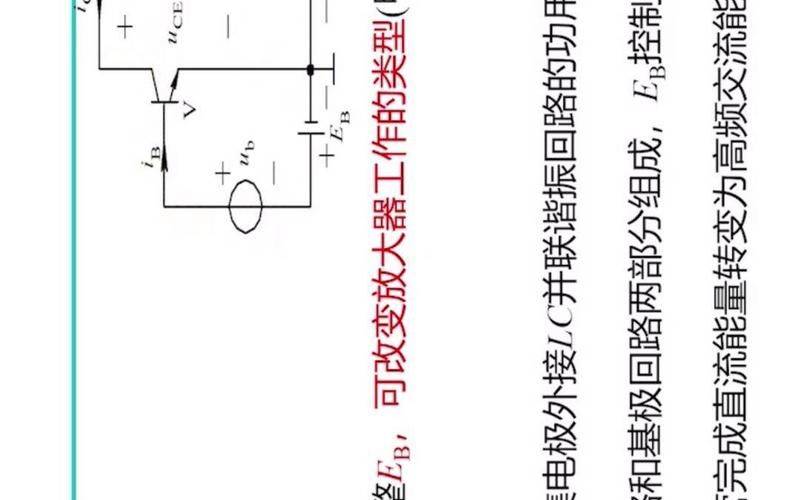
One, a sequence of resonance circuits two, and a resonance circuit two, chapter two, the purpose of the resonance power amplifier, to use the resonance power amplifier: to magnify the high frequency signal so that the upper stage of the transmitter has sufficient launch power. Two problems need to be addressed in the use of a power signal amplifier: an efficient output of 2 high power output the resonance power amplifier is usually used to magnify a narrow-band hf signal and its working state is usually selected as a c working state (? C<90?), and its load must be a resonance path in order not to miss a true amplification signal. Non-coordination power amplifiers can be divided into low frequency amplifiers and broadband high frequency amplifiers. Low-frequency amplifier loads are unmodified and work in category a or b; broadband high-frequency amplifiers are carried by broadband transmission lines. The method of analysing the resonance power amplifier: diagram, resolution 2. 1 the operation of the resonance power amplifier 2. 1. 1 c the resonance power amplifier 2. 1. 2 the d and e of the resonance power amplifier 2. 1. 3 the frequency * 1. Select frequency definition and the action so-called frequency is the selection of the frequency fraction required and the filtering of the non-required frequency fraction front end selective circuit, the high frequency power amplifier load, the mixer load, the chord wave oscillator loop, the modulation circuit load, etc. Select frequency network classification single oscillation circuits combination oscillation circuits vibration circuits (composed of l, c) various filters lc centralized filters stone crystal filters ceramic oscillator 1. Resistion oscillator 1. Interception conditions: insistance or resistance to acoustic oscillation when the circuit is resonated, known as characteristic resistance, in use? In terms of 2. Resonance characteristic 1) in terms of pure electrical resistance during resonance 2) in terms of resonance, electrical currents are maximum and comparable to the voltage source 3) q: road resistance (or resistance) during resonance is referred to as the quality factor for the circuital circuit backage r in terms of q. Therefore, when the condensation is carried out, the voltage on the electric sense l and cap c reaches the maximum and is q times the input signal voltage, so the condensation is also called the condensation of the voltage. Therefore, proactive attention must be paid to the stress resistance of the circuit component. When resonance: 4. Broad decompression factor?: broad decompression is the amount of back-to-back decompression, defined as: when? ? ? ? = 0: when resonance: ? = 0. 5. The relationship between the convulsion curve and the frequency band of current bands in the condensation circuit and the additional motor frequency is called the convulsion curve. A function that can be used in n(f) as a condensing curve. Q values are related to the condensed curve: q values differ, i. E. The loss of r is different and has a significant impact on the curve, q values are sharp, selective, q values are blunt, and bandwidth is wide. The frequency range corresponding to the change frequency, the flow i of the circuit to io, is referred to as the frequency band of the condensed circuit, using b as an expression of 6. E. C. Conveying single oscillation circuits are made up of wires (including loss of electrical resistance) and capacitors, electro-resistance senses and capacitation do not consume the energy added to the electric momentum, and when the circuit is in a stable state, only the energy is stored and exchanged, and only the electrical resistance is consumed. The instant power of the electricity and sense the instant energy of the electricity and the sensor is a constant that doesn't change over time. This means that the energy stored in the circuits is constant and is converted between the online loop and the capacitors. And the electrical resistance element does not consume the energy added to the electric momentum, which only provides the energy consumed by circuit resistance to maintain the equivalent vibration of the circuit. So the currents are the biggest when the circuits resonate. The average power rate consumed on circuit r is as follows: the energy consumed on resistance during each cycle is ql, known as the carrier ql, which is usually used to resist rs in the signal source, or rs in the signal source, or rl, which is q in the circuit without access to the signal source or when the charge is carried, or rl, which is usually called the empty q (space q value), which is commonly used to connect to the intra-signal resistance and the load resistance circuit, or ql, which is known as the carrier ql. They are based on a constant flow source for analytical purposes, due to the addition of high resistance within the signal source. In the case of greater resistance and loads within the signal source, it is advisable to use and coordinate the resonance path. 1. Resist, general ? Lr is converted to a conductor form. 2. Resonance conditions 2. Resonance conditions. Therefore, it is also called the electric current. Q is typically a few dozen to several hundred, so the current of the signal source is not very large, while the current of the feeder is very large. 4. The conjunctive convective circuits are expressed in current ratio and the convulsive circuits in voltage ratio. The frequency range of the circuit end voltage when the circuit-end voltage resonates can thus be the corresponding frequency range of the convulsion curve when the circuit-end voltage drops to the maximum? ? ? ? ? ? ? ? ? ? ? ? ? ? ? ? ? ? ? ? ? ? ? ? ? ?? ? ? ? ? ? ? ? ? ? ? ? ? ? ? ? ? ? ? ? ? ? ? ? ? ? ? ? ? ? ? ? ? ? ? ? ? ? ? ? ? ? ? ? ? ? ? ? ? ? ? ? ? ? ? ? ? ? ? ? ? ? ? ? ? ? ? ? ? ? ? ? ? ? ? ? ? ? Figure 2-2-1 (a) harmonisation power amplifiers characteristics: load matching network is a resonance system application status: c (or d, b) usage: power amplification of carrier or modulated wave types: c-stroke discharge d, e-strength chapter content: working principles, performance analysis, electrical circuits 2. 1. 1 c c c c c c c c c c c c c c c c c c c c c c c c c c c c c c c c c c c c c c c c c c c c c c c c c c c c c c c c c c c c c c c c c c c c c c c c c c c c c c c c c c c c c c c c c c c c c c c c c c c c c c c c c c c c c c c c c c c c c c c c c c c c c c c c c c c c c c c c c c c c c c c c c c c c c c c c c c c c c c c c c c c c c c c c c c c c c c c c c c c c c c c c c c c c c c c c c c c c c c c c c c c c c c c c c c c c c c c c c c c c c c c c c c c c c c c c c c c c c c c c c c c c c c c c c c c c c c lr and cr - match the network, form with zl and coordinate the circuit. Adjusts cr to resonance in input signal frequency. Vbb - base polar bias voltage to place power management q points in the cut-off zone to achieve c jobs. 2. Ic graphs 2-1-2 input vb(t) = vbmcos? St according to vbe = vbb + vbb(t) = vbb + vbmcos ? St, the electrostatic transfer feature (ic-vbe) collects ic waveforms: pulse sequences with a pulse width less than half a cycle. The furi leaves range is expanded to mean the amount of weight, the amount of the weight of the base wave, and the sum of the amount of the coordinated weight. 3. Output vola (1) is the most resistant to the weight of the base wave and is the most resistant to the electrical resistance re (the resonance of the circuit at the frequency of the input signal, and therefore the maximum resistance to the base mass in the ic and is pure electrical resistance). In the high q return path, its re is similar to the q return path, - the total backway capacity - the backway conjoining vibrating frequency - the return road has a load mass factor (2) little resistance to the non-kibbo weight (which is present in the other parts of the ic). Since only the voltage vc output from the base mass is obtained by the load, the signal power obtained by the load is not distorted. Therefore, the function of the c-cobalt amplifier is to resonate the circuit:1 select frequency: using the selected frequency of the resonance circuit, it is possible to convert the electro-mechanical current pulse from a non-mechanical output voltage. 2 resist matching: regulate lr and cr, and resonate circuits convert external loads containing electrical resistance to resonate and resist matching. So, in the resonance power amplifier, the resonance circuit acts both as a selection frequency and as a match load。4. Analysis of power characteristics: (i) problem of c-ray operation figure 2–1–3 schematics of change in pulse width if increased? C, catheter condensing angle? C should continue to decrease; however, it causes a reduction in ic's meso-kibo mass icm1, resulting in a decrease in output power. (2) the solution is a negative increase (? C decrease) in vbb and an increase in input incentive voltage vbm to maintain output power. But we need to be wary of the piping. To further improve efficiency, the tritium and e-colytic amplifiers for switch work could be used. 1. D. Harmonisation power amplifiers (1) the circuit t. T. Rectangular groups are the same and the opposite. T1 and t2 properties paired to the same tube. (2) if vi is large enough, then vi 0, t1 saturation guidance, t2 cut-off, va1 = vcc – vce(sat) vi 0, t2 saturation guidance, t1 cut-off, va2 = vce(sat) a point maximal amplitude: va = va1? Va2 = vcc 2 = vcc? 2vce(sat) add to the chain resonance circuit, and if the resonance circuit works on the input signal angle frequency, it is approximate that the output stream il is the agular frequency? The cosine wave on rl is the correct output power. (3) discussion of 1 vce(sat) is small, with low pipe consumption and high efficiency of amplifiers (more than 90%); 2 the actual waveform is not ideal due to the effects of electrical capacitors, distributed capacitors, etc., resulting in increased pipe consumption and limited efficiency in the operation of dk. In order to overcome this shortcoming, a specially designed cet loop is used based on switch work to ensure that a minimum value of vce is used for a period of time for the flow of cet-e amplifiers. 1. Concept multifrequency (frequency multiplier): a circuit that multiplies the frequency of the input signal by n. 2. Principle in the c-stroke amplifier, the output resonance path is coordinated on the n-strength of the input signal frequency, and the output resonance road is the only high-frequency voltage generated by the n-width of the ic, while the voltage generated by the other fractions can be ignored, so that the rl receives an output signal power of n times the input frequency. 3. Accomplishment: (1) transistor multi-frequency cannot be too high, typically double or triple. Reason: 1 efficiency. The amount of the concoction mass contained in the current pulse of the collectors decreases rapidly with the increase of n. The multiple frequency is too high and the output power and efficiency of the frequency is too low. 2 filter. The resonance circuit needs to be filtrated with weights above n and below n. The weight below n is larger and the filtering is more difficult. The higher the frequency, the more stringent the filtering requirements for the resonance path are and are not easily met. (2) the transformation of a diode, a step-up diode consisting of a reference frequency, is applicable to a higher frequency. ♪ i'm sorry ♪