Those who did the emc modification know that the best thing in the lab is magnets and copper. I can't tell you how hard it is to put a magnetic bead on it, then put a piece of copper on it, and it's impossible to put a shield on it -- the three axes are finished, the radiation's still above the mark, and the transfer is impossible. To put it bluntly, these tactics are not unhelpful, but rather have been used wrongly rather than in more trouble. Today, open the three most common faults in the emc overhaul and see how many you stepped on。
Miss one: magnetic bead one on the signal line. Magnetic beads aren't all-powerful filters. Device
Emc tests never took place, and many people's first reaction was to put a magnet on the signal line. I think the magnets can filter the hf, but they don't add up. This idea is correct, but it is often implemented with problems — worse than not。
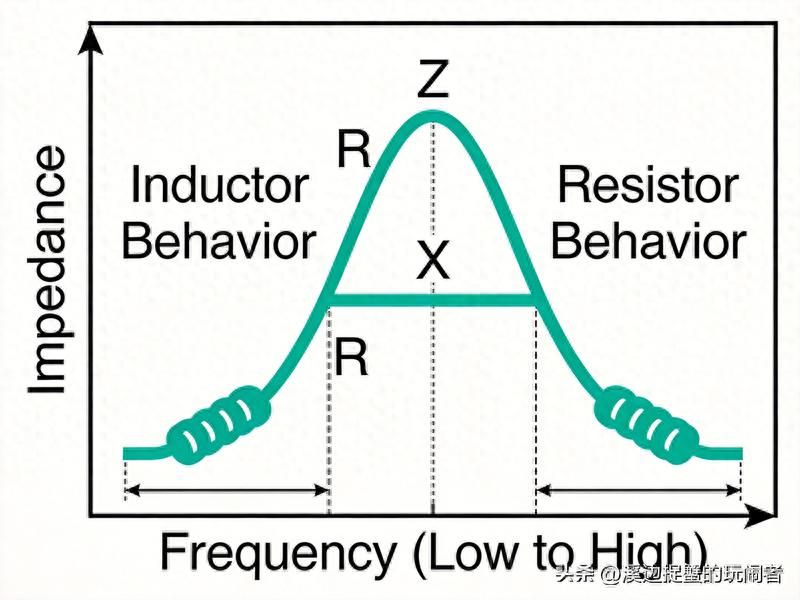
The resistance properties of magnetic beads are associated with frequency: sensory at low frequency, equivalent to a small electrical sense; resistance at high frequency, which converts high frequency energy into heat consumption. The point is that magnetic beads have a fixed resistance to peak frequency, and different models vary considerably. If the interference frequency you want to suppress is not close to the magnetic bead's resistance peak, the bead is either less sensitive or less resistant than the true filter effect。
2. Typical consequences of false magnetic beads
A more common error is the placement of magnetic beads on high-speed signal lines. For example, signals like usb, hdmi, spi, which themselves rise steeply, have a wide spectrum, and the low frequency sensitivity of magnetic beads slows the edge of the signal, closes the eye map, and miscommunications. You think you're filtering interference, actually destroying the signal. In another case, the magnetic bead is attached to the power line but does not match it, the magnetic beads are electrons at low frequency and the back-end convulsion forms the lc and the texture is larger。
3. Correct use of thinking
The correct use of magnetic beads is based on three prerequisites: first, the identification of jamming frequency points, then the selection of models that resist the alignment of peak values, and finally, the confirmation that the quality of signals is not affected. Low-speed signal lines (i2c, uart, gpio) with magnetic beads have little impact and can be used boldly; high-speed signal lines should be used with caution and replaced with a commodity sense, if necessary, with a low impact on differential signals and a good effect on inhibiting commo interference. The power lines are wired with magnetic beads, which must be combined to form the lc filter network。
Corrective steps: positioning the source and frequency of interference before deciding which model to use instead of magnets. Blind magnets cover problems, not solve problems。
Zone two: the line is just one line
The emc was the most problematic site-to-place. Many people feel that the line is finished, that the ground is connected and that the floor is covered. However, the site approach is much more important than the number of sites, and the interference is wrong, not less, but rather connects the other modules through the line。
The most typical error is the multi-point formation of the ring road. The two modules are connected by both signal and by different paths, and the circulation is detected in the loop when the external magnetic field changes, the level of electricity is no longer the same, and the co-mode interference is directly associated with the signal. This is particularly common at industrial sites — where sensors and hosts are separated, where major circuits are formed, and where transmissions are launched, the signal is disrupted。
2. Simulation of random short-range numbers
Another common error is that of connecting analogies directly with numbers. The combination of adc and dgd chips, which are marked with agnd and dgnd, is considered by many to be the same location and the direct short-term connection is fine. But the interior simulation and the digital field of the chip is created separately, and you are randomly short-linked on the pcb, and the digital switch noise is filled with simulated ground level by short points. Adc's lsb jump code and dac output pricks often have roots here。
The correct approach is to connect the chip at a single point under the chip, with the shortest flow path within the chip. Far from the chips, analogies and numbers remain independent and noises do not interfere with each other through ground level。
Three, the shell and the signal
The function of the crust is to release static power and waves, and the signal is the circuit reference level, which is completely different in nature. Some designs link the signal directly to the shell, the esd discharge path on the shell, the large current transient signal on the wave discharge path is directly injected into the signal, the light system is reset and the chips are burned. Controlled connections need to be made between the crust and the signaled ground - with a single m block of resistance and 0. 01 m f, or with magnetic beads to make the connection point resistant to control, rather than simply short-linking。
Wrong area three: the shield covers everything. The rationale and conditions for the shield
The shield seems to be the most cost-effective -- radiation exceeding standards? Cover up. However, the effectiveness of the shield depends on three conditions: conductivity continuity of the shield, low resistance of the site, and filtering of access cables. Without one of these conditions, the shielding effect is significantly reduced. Many designers cover only the masks, which, regardless of these three conditions, result in radiation or excesses, adding to bom costs and assembly difficulties。
2. Gaps and openings are the biggest holes
The biggest enemies of the shield are cracks and openings. Electromagnetic wave leaks are proportional to the length of the gap and work wave lengths are inversely proportional. A 2cm gap, which is a half-wave-length gap antenna at a 1ghz frequency, is highly radioactive. In the actual product, the seams of the shield, the screw hole, the heat hole and the pointer opening may be leak channels. Many times you think you're wearing a shield, and it's actually leaking a little bit。
The solution is to fill it with a conductor liner at the seams, with a wave catheter structure for the dispersing hole (a good decline in the depth of the hole greater than five times the aperture), and with guidance glass for opening the light. These details are not done. The shield is set。
Three, access cables are invisible killers
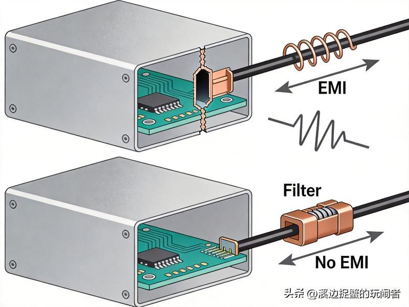
The shield is so tight that a cable without filters is a waste of effort. Wires are the most effective radiation antenna, and internal interference is connected to the cable, which directly emits the energy, and the shield becomes a convulsive cavity, magnifying the interference and irradiating through the cable. This is often seen in modifications: it is barely possible to pass without a shield, but the radiation is higher with a shield because the cable is not filtered and the shield cavity is reinforced。
Correct practice: wires into and out of the shield must be filtered through the wall, signal lines must be filtered through the heart or feed filter, and power lines must be filtered. If the cost is not permitted, at least magnetic + capacitor filter networks at the entry and exit ports. If the cable problem is not resolved, the shield is useless。
The correct way of thinking: locate the source, then do one, first diagnose and then square
The most taboo thing about emc reform is that it starts without locating the source. The radiation is overrated, and it is clear which frequency points are over, different models or comprehensible models and which cable is coming out. Scrutinize the location of the jamming source with a close look and decide on the remediation programme. Magnetic beads, flooring and shielding, each of which has a suitable scene, can only be wasted。
2. Control of interference from source
The priority of the overhaul should be to discourage sources over cutting transmission pathways. The clock's up too steep. Can you slow down the margin? Could you adjust the frequency of the switch frequency coordinated by the switch to the sensitive frequency? Can you pull long distances when the noise and sensitive circuits are too close? Reducing the amount of interference from the source is much more efficient than blocking the transmission path。
3. Design phase prevention is better than aftercare
To be honest, most of the emc problems were buried in the design phase. The layout does not have partitions, the decorated capacitation is not in place, the floor is cut to zero and the cables are not filtered, and these problems are fixed at 5 to 10 times the cost of prevention during the design phase. The real cost-saving approach is to take emc into account at both the motion map and pcb stages — layout partitioning, ground level integrity, key signals filtering, pre-positioning of filters at connectors. A little more in the prior period and much less in the later period。
Summary
The modification of the emc's three largest faults — blindly reinforced with magnetic beads, obscuring the ground and over-shielding — is essentially a direct result of unpositioned problems. Magnetic beads are selected in pairs and positions; the site is divided between functions and control of connections; the shield is to ensure continuity and handle access cables. The correct sequence is that the most effective means of inhibiting the choice of the route for the analysis of the source of interference. The more fundamental idea is to prevent the emc problem at the design stage, rather than wait until the test is completed。