Introduction: lu bingin (1936-), male, liao ninghian, professor, studies in the control system digital simulation and cad, theory and application of the intermittent control system. E-mail: 13263430051@163. Com
1 method of measuring power
The power absorbed by the charge is:

If the baseline resistance value r1 = 8 times. According to formula (2), the power p1 of the base voltage slot u1m = 10v, calculated in matlab language programming, corresponds to voltage u1, as shown in table 1。
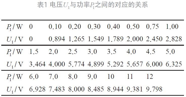
Scale power on the dashboard by table 1. If the voltage is too high to exceed the limit, the limit shall be increased by 1 α, i. E
Or... It's written in a popular, i-voltage file
(i = 2, 3, 4, ...). If the electrical resistance of the measured power is not eight times, it is
, according to (1):
Format (3) expresses the correspondence between the actual power of pi and the indicator power of p1。
Of which
(b) beta is called the resistance correction factor for power. If a slotting measure is performed at the 2nd slot voltage (u2m = 50 v), that is
;and when measured rn = 4 times, i
, when indicating p1 = 2. 3 w, the actual power:
2 error analysis for power measurements
As the power of the base voltage slotting is measured, the text symbol in formula (1) is marked down to 1. P1 calibrates u1 and replaces d with gypsies
Form (4) divided by form (1), with reconsideration (2), to obtain the absolute value of power error:

Of which
The basic error absolute value of the voltage slot is exchanged for the baseline. Mode (5) the relationship between power error absolute value |γp| and base voltage u1 is obtained through the matlab language programming, as shown in table 2, as shown in figure 1。
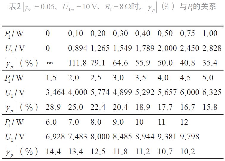
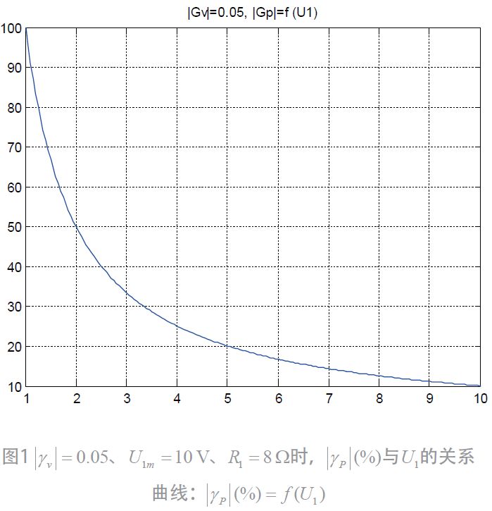
Note: |gv in figure 1 is |γv| and |gp is |γp| (%). As can be seen from formula (5) and figure 1, gamma p (%) is inversely related to u1, i. E. |γp| (%) decreases with the increase in u1. So if the pointer is as close as possible to the full scale, how is the range of the pointer selected
3 indicator range at power measurement
As noted in table 1, the upper limit for the base voltage slot (u1m = 10 v) is u1b = 9. 798 v (the corresponding power cap p1b = 12 w). For example, u1m = 10 v, u2m = 50 v, u3m = 250 v, u4m = 500 v, u5m = 1000 v
, same α3 = 25, α4 = 50, α5 = 100. When beta = 1, the formula (3) gets pi =
(i = 2, 3, 4, 5) received:
1) maximum power of the staggers: as indicated in table 1, the maximum power of the base voltage staves is
= 12 w, the upper limit for other power slots by pattern
Calculate。
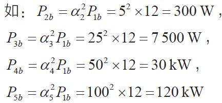
2) the lower limit of power in each class is the upper limit of the lower range:
3) the upper limit of the power indicator for each stage
4) lower limit of power pointer indicator for each stage
Calculate。
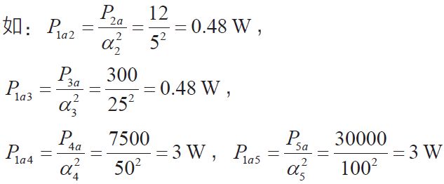
It's too low to be accepted because of the error. On this basis, voltage slotting ranges, power correction values, power measurement ranges and pointer indicator ranges are shown in table 3。
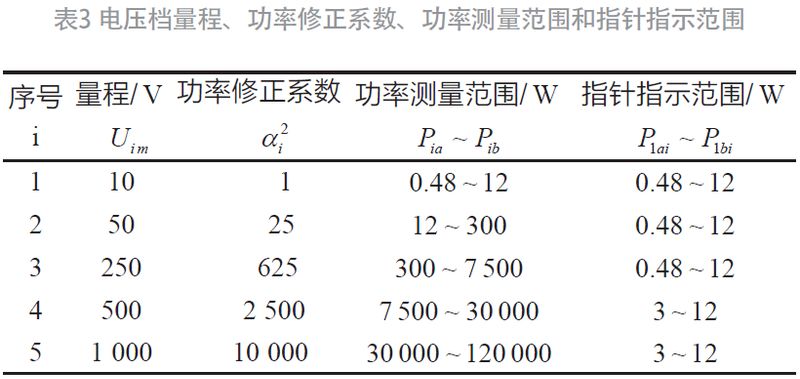
Table 3 shows the minimum power of 0. 48 w as indicated by the pointer. The greatest error occurred at this time。
Substitute (5) shall:
That's a considerable value。
4 power measurement method (refer to power correction factor in table 3)
For the safety of the universal-use meter, the power real value is first measured by a maximum voltage slot, e. G. 1,000 v; the indicator multiplied by the power correction factor of 10,000; if the indicator value is less than 3 w, the power real value is reduced by 1 level v, measured by 2,500; if the indicator value is less than 3 w, by 1 level v, measured by 625; and if the indicator value is less than 0. 48 w, the power real value is reduced by 1 level, and so on. If the benchmark voltage slot indicator is still below 0. 48 w, it is not acceptable because of the error. Note: when the measured resist value is not eight, the power resistance correction factor should be considered. Example;rn = 4 times, measured in u2 = 50 v
= 3 w check table 3
If no table 3 is available, it can be calculated
Requiring p2 from the top. Actual capacity
= 25, resistance correction factor for power
5 concluding remarks
Power and level measurement is an additional feature of a universal meter. Other additional features are telemetry, electro-capability measurements, and transistor straight flow magnification multipliers. With the exception of the last one, there are no circuit design and calculation problems involved, except the calculation of the scale of the measured value relative to the base voltage, which is then written on the tablet. In addition, in the case of error analysis, since the first four elements (electricity, power, perception, electricity) use an exchange voltage slot, the error is proportional to the fundamental error of the exchange voltage slot. The fundamental error of the exchange voltage slot is a combination of basic errors at the top of the surface and electrical circuit resistance and current processors. In addition, power and electro-level error curves are reduced by the increase in measured values, which are different from those of resistance, sensory and capacitation, where the error curve rises at both ends. This paper gives an indication of the range of the tensile scale pointers from the perspective of reducing measurement errors. Users should pay special attention to the use of universal power meters. Mention should also be made of the zero flat power p0 = 0. 001 w, the zero flat resistance rn = z0 = 600 and the basic resistance r1 = 8 in this paper. According to formula (3), the level of its base voltage slot (α1 = 1) is:
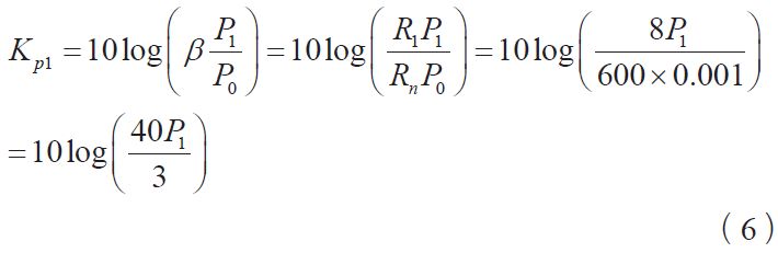
Or the function for which p1 is expressed as kp1, as follows:

Format (6) or (7) indicates a correspondence between the level of power and the power. So, in the schedule scale of the mp, the kp1 and p1 scales do not normally appear simultaneously. Because once one is measured, the other can easily be obtained through the formula above. Finally, it should be noted that in the technical instructions of the miller, the error given is the relative error in the full-volume range, which is certainly small, such as 5 per cent. In practice, this should be taken into account by the maximum error at the time of measurement, which is 51 per cent. This is only possible if the measurement methods are correct。