This is a design and rationale for the refrigerator door alarm circuit, using a 555-timer and photo-sensitive electrical resistance (ldr). When the refrigerator door remains open for a long time, the circuit triggers the alarm. The circuit uses 555 timers to work in unstable multi-cobalt oscillators and the light-dependent properties of ldrs. If the refrigerator door is opened, the light is irradiated on the ldr, which reduces its resistance, leads to an electrical discharge and activates the alarm after a certain time. The design was designed to alert users when the refrigerator door was open for long periods in order to save energy and protect refrigerator compressors。
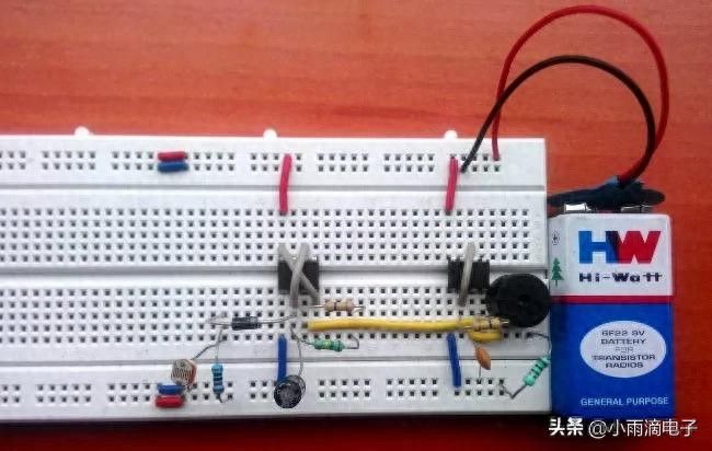
Compo– 1 no. Diode (1n4007 or 1401) – 1 no. Capacitor, 47u f (electrolytic) – 1 no. Capacitor, 0. 1u f (ceramic) – 1 no. Resisters (10kὨ-1; 470kὨ-1; 150kὨ-2; 100Ὠ-1)Nicking wirres principles
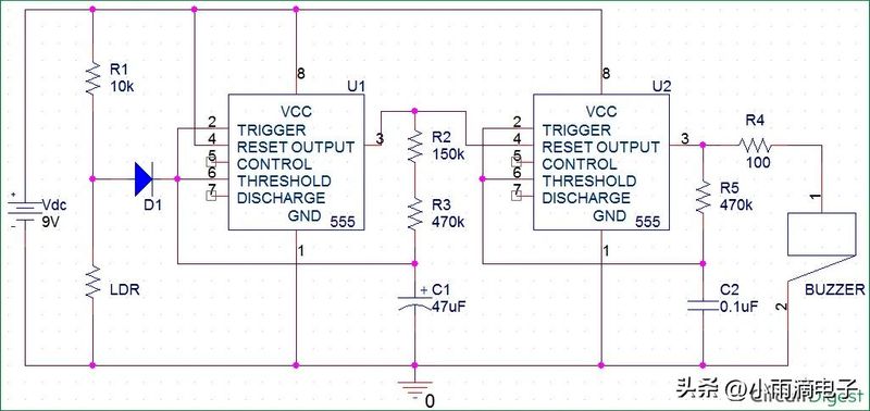
The circuit is powered by 9v batteries. When the refrigerator doors were closed, the photo-sensitive electrical resistance (ldr) was close to 1m times due to insufficient light. At this point, the output voltage of the level subvoltager is attached to the capacitors so that it remains charged (more than 2/3vcc) and the output is low. When the refrigerator door was opened, the light was exposed to ldrs, which lowered their resistance, resulting in the discharge of the capacitors, which took approximately 30 seconds in the rc combination. After that (lower than 2/3vcc) the output begins to oscillate at a specified frequency and the output becomes high-level. The capacitors are then recharged and reach the threshold, followed by discharge. This process ceased when the ldr barrier was raised (no light, i. E. Door closure)。
This caused the second 555 timer to start oscillating and the output of the high- and low-altitude alternation, making the beeper connected to the output sound in a pattern made from the first timer oscillation and the second timer internal concussion combination. When the first timer output a high level of power, the second timer is triggered by the primary recovery. As a result, c2 capacitors were charged (high voltage above 2/3vcc) and the output was reduced. In a short period of time, the capacitors start dischargeing (with a voltage of less than 2/3vcc) and the output becomes higher. Thus, the beeper that connects to the output sends a pulsed beep。
Time
Time (sec) = 1. 1 x (r2 + r3) x c1Time to open the fridge
Time (sec) = 1. 1 x (620kὨ5%) x 47uf
Time = 30. 4 secs
Thus: r2 = 150kὨ, r3 = 470k Ὠ c1 = 47uf
Beep time
Time (sec) = 1. 1 x (620kὨ5%) x 47uf
Time = 30. 4 secs
Therefore..
R2 = 150kὨ,
R3 = 470k
C1 = 47uf