An electric sensor is an electronic element used to introduce a sense into the circuit in order to resist changes in the size and direction of the current, even if a direct conductor may have a certain amount of a sense。
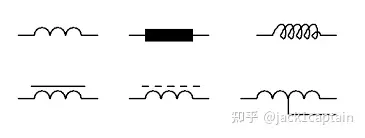
Electric sense symbol
The concept of electrons
An electric sensor resists or opposes changes in the current, but it can easily pass through a steady state current. The ability of sensors to resist current changes is also linked to the current i as a proportional constant of its magnetic link nΦ, known as the electrons, with the symbol l, in henry, (h) named after joseph henry。
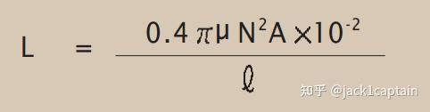
Definition of electrons
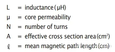
The electrons circle has a central magnetic core area (a), and the number of lines (l) per unit length is constant. So, if the n-string is linked to a certain amount of magnetic flux, the circle has a n-thing magnetic chain and any current (i) flows across the circle creates a flow of sensory magnetic fluxes in the opposite direction. So according to faraday's lawjack1captain: preliminary magnetic field, any change in this magnetic link will generate a self-sensitized voltage in a single wire:
The zirconium is the flux of the webs
Di/dt current change rate in amber/s
The magnetic field sense of change over time is proportional to the rate of change in the current that produces it, with positive values indicating an increase in the electrical dynamic and negative values indicating a decrease in the electric dynamic. Replace μn2a / l with l (expressing the ratio constant, known as the telekinesis) to find equations associated with self-receptive voltage, current and sensory.
Electric voltage (electrically)
Of these, l is electrons and di/dt is current rate。
One sentence explains that electrons are the same as electrons multiplied by current rates。
When a steady state of straight current flows through the electrical sensor, the sensor is equivalent to a short circuit of a wire or at least a very low-value resistance. So, for televoltaic voltage, be careful whether it's communication or direct flow。
The current and the voltage in the electrons
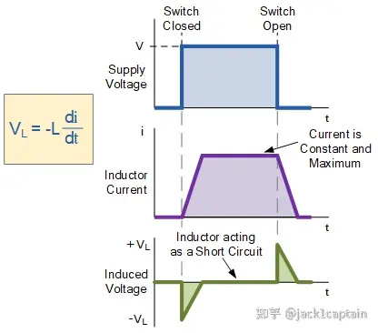
First, the two maps above describe the charge and discharge of the sense. But it's an ideal state, and the second telekinetic dynamic is actually problematic, for formulas:
We can see that if the di/dt slope is certain, then the generated motor will be a fixed value, not a vl status in the above figure。
So the above reference diagrams are just to help us understand the relationship between telepathic power dynamics and currents。
Here's a real case, or maybe more case in working life:
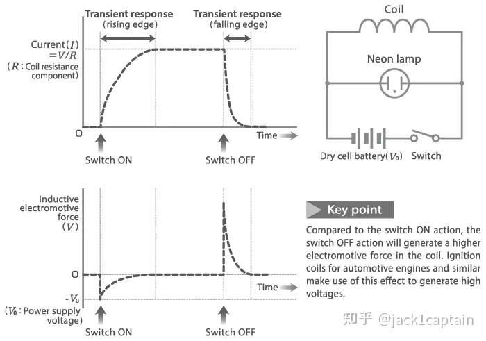
Https://www. Tdk. Com/en/tech-mag/electronics primer/2
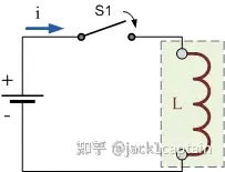
The above is a picture of the tak official network, describing the neon switch. When the switch switch leads, the electrons coil is charged, the first image of the electrons flow, which starts to slow behind the charge, and we will find out in the subsequent lr charge circuit. However, when the switch is off, the energy on the sensor is released into the combined neon lamps, and there is no external power source, so the initial current changes in discharges are significant, and this rapid change in di/dt creates a very large induction dynamic, as shown in the second figure. That's the principle of blinking neon lights。
The energy in electricity
The extrapolation process is not exhaustive. W=pt=vit, which can be obtained by replacing the voltage with a formula。
Real sensors always have some electrical resistance associated with circuital circuits, and as long as currents pass through resistance, energy is lost in heat or constant according to om's law (p = i2r). The main uses of sensors are filtering circuits, resonating circuits and limiting currents. An electric sensor can be used in circuits for the blocking or plastic exchange of electricity or a series of sine frequencies, in which the sensor can be used to “modify” simple radio receivers or various types of oscillators. It can also protect sensitive equipment from destructive power peaks and high wave surges。