
In a car brake system, a vacuum booster (also known as a vacuum server pump) is a core booster. It is like an invisible “heavy” that silently magnifies the driver's power to press the pedal, making brakes easier and more efficient, especially in the case of heavy vehicles or high loads. The work logic of vacuum boosters will be fully analysed from core principles, structural composition, workflow, common types and five dimensions of failure。
Core principle: “enrichment of the negative pressure of the vacuum”
The work of vacuum-assisted pumps is by nature a clever use of pressure differentials between “vacuum side” and “atmosphere side” to drive the piston to generate additional help, thereby reducing the brake strength of the driver. This rationale is based on basic physical logic: atmospheric pressure is about 101 kpa, and when a “vacuum environment” (pressure close to 0kpa) is created within the pump, the “atmospheric side” and the “vacuum side” create about 101 kpa pressure differentials. This seemingly simple pressure is poor, and it contains a huge energy that can be converted into mechanical thrusts, added to the pedals of the pilot, which together drive the brake main tank to produce high-pressure aerodynamic fluids, and eventually brakes。
In order to better understand this rationale, we may wish to make an image analogy. It's like using a straw to drink a drink, and when we suck a straw, it creates a vacuum (negative pressure), where external atmospheric pressure works, and the drink is “pressed” into our mouths. Vacuum booster pumps work in a similar manner, except that they use this pressure differential to “push” the brake agency for the purpose of braking。
Ii. Key structure: complete work on the 4 major components
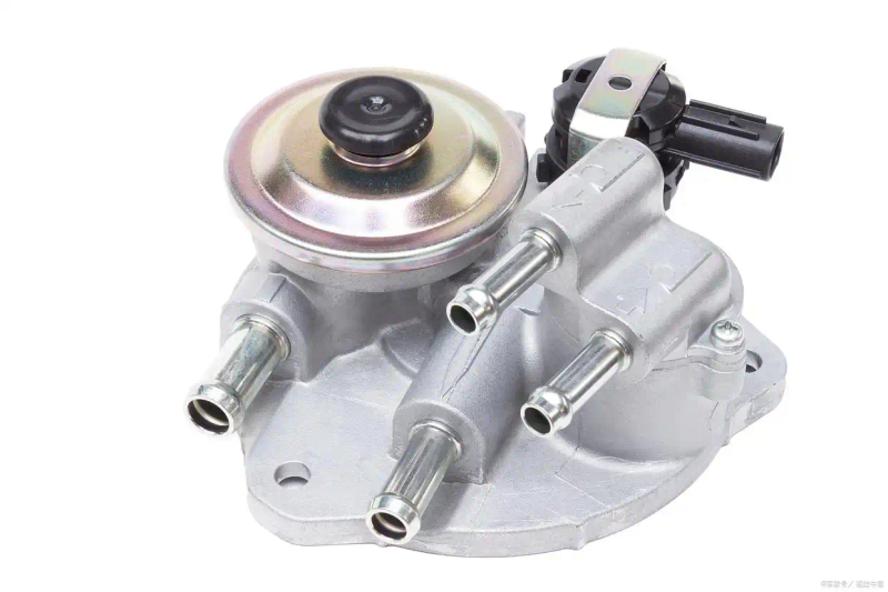
In the case of the most common “vacuum enablers” in cars, vacuum boosters are usually integrated into the brake main tank, structured into four core parts of the “vacuum cavity” “atmospheric cavity” “film/pistol” “control valves”, each with a specific mission。
Vacuum cavity
Located on the left side of the booster and connected through the pipe to the engine entry airway or electric vacuum pump. Its main task is to maintain a long-term vacuum (pressure ≈kpa) as a “negative side” to provide the basis for the generation of stress differentials。
Atmospheric cavity
On the right side of the booster, connected to the atmosphere or vacuum cavity by the control valve. It has interchangeable properties that enable it to achieve an “atmosphere” or “a vacuum” as required, which is “on the side of pressure change” and is a key area for the formation of stress。
Films and pistons
This is a tacit partner, and the film is a flexible component that separates the vacuum cavity from the atmospheric cavity, usually using rubber material, with good elasticity and sealability; the piston is a metal material connected to the film. Together, they are driven by stress differentials, which translate into mechanical thrusts and are transmitted to the brake main tank, and are key to enabling transmission。
Control valve
At the top of the booster, closely connected to the brake pedal. It is like a precise “commander” who controls the “break” of the cavity with the pedal. The atmospheric cavity is vacuumed and pressures are balanced on both sides when no brakes are put on; when brakes are put on, the cavity of the atmosphere reaches the atmosphere, creating a low pressure, which activates the assistive function。
Full workflow: 3 phases of precision
The work of the vacuum booster pump is closely linked to the driver's brakes, and can be divided into three stages of “free brake” “dismantling brakes”, each stage of which changes in pressure and the movement of components are clearly identifiable。
Without brakes: stress balance, helpless
At this point, the driver did not step on the brake pedal and the control valve was in "initial position". It connects the “atmospheric cavity” to the “a vacuum cavity”, making it a vacuum. Because the vacuum cavity is consistent with atmospheric cavity pressure (both vacuums, ≈0kpa), the film/pistol side is free of pressure and therefore does not generate thrust. The brake system is dormant and the vehicle is moving normally。
Brake in progress: stress is helping
When the driver steps down the brake pedal, the pedal pole drives the control valve, and a hand-held “magic” goes on. First, the control valves cut the passages of the “atmospheric cavity vacuum” while opening the channel of the “atmospheric cavity outside” to allow the atmosphere to enter the cavity. With the influx of the atmosphere, the atmospheric cavity pressure rose rapidly to 101 kpa (atmosphere pressure), while the vacuum cavity remained at 0kpa, creating about 101 kpa pressure differentials on both sides. This powerful pressure difference drives the film/pistol to the left, holding the “drive main cask pusher” at the front end of the piston, putting together “the driver's pedal force + the force of the pressure differential” to drive the brake main cask together to produce high-pressure aerodynamic fluid. These brake fluids are transported to the four-wheeled brake subpump, driving the brake blades in close contact with the brake plate to achieve the brake purpose. It is worth mentioning that the greater the pedal, the greater the “atmosphere channel” opened by the control valve, the more stable the pressure, the more sustained the help effect, and the positive correlation between the force size and the pedal trip。
When brakes are removed: pressure rebalancing
When the driver releases the brake pedals, the pedals drive the control valve. The control valves close the passages of the “atmospheric cavity outside the atmosphere” and reopen the passages of the “atmospheric cavity vacuum”. At this point, the air in the cavity is inhaled into the vacuum cavity (the vacuum cavity continues to eject through the engine) and the pressure on both sides is again consistent (both vacuums). The membrane/pistol returns to its initial position as a spring of return, the brake pressure on the main cylinder disappears, the brakes are lifted and the vehicle returns to normal condition。
Common types: 2 mainstream vacuum sources all
The core premise of vacuum-assisted pumps is “continuing provision of a vacuum” which, depending on the source of the vacuum, is divided mainly into motor-injective and electric vacuum-pump types, each with characteristics and applicable scenarios。
Engine inbound (traditional fuel vehicle mainstream)
In conventional fuel trucks, motor-injection vacuum booster pumps are the main choice. The vacuum results from negative pressure generated by the operation of the fuel engine. When engines operate, negative pressure is formed within the inlet tube (the smaller the air-saving door is open, the stronger the negative pressure), and the vacuum is introduced into the vacuum cavity of the booster pump through the pipe. The advantages of such an approach are obvious, as it does not require additional power, is simple, cost-effective and reliable. However, it also has some limitations. As a result of relying on engines to operate, when the engines are out of fire, the entry tube is free of negative pressure, the booster pump can only maintain one or two effective boosts, and subsequent brakes will become very heavy. In addition, the effect of the contribution may be diminished when the pressure of the input tube is insufficient at low turning speeds and heavy loads (e. G. At an acute acceleration). Thus, it applies mainly to the vast majority of conventional fuel cars, suvs。
Electric vacuum pump (new energy vehicles/part of high-end fuel vehicles)
With the rise of new energy vehicles, the electric vacuum pump-type vacuum booster pump gradually emerged. Its vacuum originates from an independent electric vacuum pump, powered by a 12v/24v vehicle-borne power supply. An electric vacuum pump creates a vacuum through an electric-driven pump and is equipped with a “vacuum pressure sensor” to monitor the vacuum in real time. When the vacuum is below the threshold, the generator starts the vacuum; when the threshold is reached, the generator ceases to work. The advantage of this approach is that it does not depend on engines, and even before the engine goes out or electric cars are powered (low-pressure batteries) it will maintain a vacuum and the brakes will be more secure. Moreover, the vacuum is stable and is not affected by engine conditions. However, it also has a number of disadvantages, which require a slightly higher cost of additional electric pumps, sensors, control modules, and the consumption of a small amount of electrical energy for long-term use (but with minimal impact on the continuation of electric vehicles). It applies mainly to new energy vehicles (pure electricity, mixing, engine-free entry tubes), turbine fuel vehicles (lower charge of gas entry tubes after turbo intervention) and high-end vehicles (pursuant brake stability)。
Key supplements: “defunct tips” for vacuum booster pumps
Vacuum booster pumps are not indestructible and, in the event of malfunctions (e. G. Leaks in vacuum pipelines, damage to electric pumps, fractures of film, etc.), may result in insufficient or non-functioning enablers, posing a serious threat to the safety of pedestrians. At this point, the vehicle sends out some “suspense signals”, which the driver needs to detect in a timely manner. Typical performances include: heavy brake pedals, which require much more than normal force and shorter pedals; longer brake distances, which significantly diminishes the brake effect even if the pedals are pressed; in the case of fuel trucks, a leak in a vacuum pipe leads to abnormal motor intakes, a lack of speed and a lack of speed; and, in some cases (especially in the case of new energy vehicles), a “branch system failure” or “vacacity pump failure”. When the above occurs, the driver shall immediately stop the vehicle and avoid the risk of brake failure。
The nature of the vacuum booster pump is “to create pressure differentials with a vacuum negative pressure and to convert atmospheric pressure into brake aid”. Traditional fuel vehicles rely on the “loan” of the engine, and new energy vehicles rely on the “made” of electric pumps, all with the ultimate aim of allowing the driver to “lightly press the brakes with a heavy effect”. Understanding the working principles and common problems of vacuum-assisted pumps will help us better maintain vehicles and ensure road safety。


