Amateur radio enthusiasts, who pass the c class test, can use high power in short-wave amateur bands. Indeed, the majority of amateur radio fans prefer shortwave connections with less than 100 watts of radio, even lower than the low power of 5 watts, and green connections with micropower less than 1 watts, which i have promoted most. But there are times when it is really necessary to use power to complete a connection. For example, when pursuing rare expeditions, opening power amplifiers can be effective in order to cross a powerful japanese wall, and participating in international competitions for large power groups, where power is essential. Therefore, it is also necessary to have a short wave power deployment if personal conditions permit。
Short wave power amplifiers are divided between transistor tubes and electrode tubes, which are typically used as electronic amplifiers by transistor triodes or field effect tubes, whereas electrode applications are used as electronic amplifiers by vacuum electronic tubes or ceramic radar tubes. The advantages of a transistor operation are efficient, efficient, long life and small overall size. It is very easy to use and can be launched immediately. The shortcomings of electro-channel deployment are precisely the advantages of transistorization. However, one of the strong advantages of electronic piped power is resistance to “making”. Many national armies are said to have been stockpiling large amounts of electronic pipe communications equipment in order to resist powerful electromagnetic pulses in future wars. Electromagnetic pulse strikes have become an indispensable means of attack in modern warfare. Their effects are radar, communication systems that quickly blind the enemy at the beginning of the war; the army has demonstrated, through extensive experiments, that the communication, radar equipment of electronic tubes can withstand a certain intensity of electromagnetic pulses. For amateur radios, friends who have used transistor and electron applications may have the same experience that electronic tubes are used in a solid manner, and that they are not susceptible to damage (a very strong overload), and transistor and field effect tubes are vulnerable to damage. The body will be deeper, because of its own careless operation, and the n power field effect tube will be burned. It's heartache! So i love the electro-channel。
Since i love e-manufacturing, of course i'd like to actively recommend e-manufacturing to ham! Many of the country's business friends also produce and sell short wave credit. Sales have been good, and some of the refined products have also been sold abroad, and have received favourable international feedback. Some products are pro-people and cheap and are praised by a wide range of ham. There are also many friends who have built their own short wave electro-channels, using their own diy devices for remote dx connectivity, and a very special experience. The diy process itself is a very happy experience. So, i'm in favor of a qualified ham friend who, under the guidance of a professional, is doing a dey short wave. Here, i'm giving you some information about radio lovers who like to use short wave electro-channels and want diys。
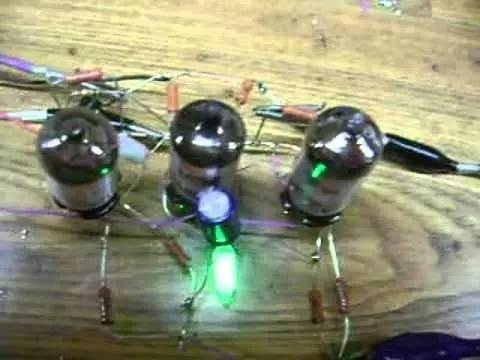
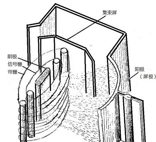
General structure of electronic tubes. General electronic tubes are shelled by vacuum glass tubes, and there are electrical poles made of special metal materials. The electrodes are classified as anodes (screen poles), cathodes and fences. The poles are divided into fences, drapes, control fences, etc.; the cathodes are also divided into heated cathodes and filamentals。
General working principles for electronic tubes. When the wiring of the tubes is accompanied by electricity, the temperature of the wiring increases, although in a vacuum, thermal radiation of the wiring of the wiring increases the temperature of the cathodes, which reach a certain temperature (around 800 degrees c), and the electrons on the wiring around the cathodes to form charged electrons. When a high voltage is added between the cathodes and the anodes (screen poles) (extremely negative and very positive), in accordance with the principle of heterosexual insulation, the negative electrons that drift through the electron cloud around the cathodes pass through the poles and run towards the anodes to form an electronic beam, which is like an electronic switch. When the fence is non-powerful, the electron flow stabilizes through it to the anode (screen pole); when the poles are added to the positive voltage, the electrons in the cathode are attracted, increasing the speed of the electron flow and the amount of the charge; when the poles are added to the negative voltage, the cavity becomes a barrier to the negative charge due to the principle of homophobic repulsion, and the charge has to be driven by a long distance to reach the anode (screen pole), significantly slowing down the movement of the electron flow and reducing the number of negative electrons passed。
In fact, the same principles are used for the amplification of electrode and transistor triodes, and the electro-barrel, like the base pole of the transistor tripolar tube, can create a larger voltage or current between electro-code cathodes and the anodes with the same changes in the shape of the cathode input, which is the principle for magnification of the general electrode. There is also a concept of "cross-guided" in the electrode, which is slightly the same as the "magnification multiple" of the transistor triode。
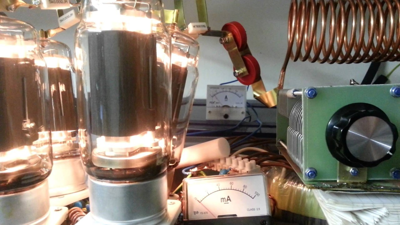
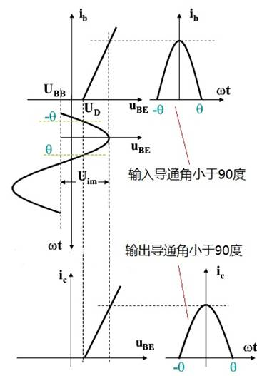
It's about the linear magnification of the tubes. Linear amplification is defined as a proportional magnification in the working state of transistor tubes and electronic tubes within their own characteristic curves, equivalent to the input signal, also known as alpha magnification. However, short wave power upper amplifiers typically work in c or ab, and loads are generally lc-coordinated circuits, with a conductor angle of less than 90 degrees. Empirical values tell us that a general conductor angle is most efficient at 70 degrees. Such a design would make amplifiers work efficiently, with high and low power. For example, a single fu-13 electronic tube is generally exported less than 60 watts at work in category a. However, if the work is in category c, the output can be up to 600 to 700 watts, and the power required is significantly reduced and its efficiency improved. How do we get electrode and transistor amplifiers to work in category c? This requires that, in the design of the circuit, the working state of the tube be determined, so that the tube works between the linear and non-linear nature of the characteristic curve by adjusting the negative bias of the transistor tube and the negative fence data of the electronic tube (see the rationale chart)。
It appears that electro-channel discharge circuits are simple (see my fu-13 short wave electro-channel discharge rationale) because of the high-power short wave discharge screen pressure of 2,000-3000 volts. Because of this high pressure, it's true that the amateur radio fan, diy, has become the rover. But we are basically safe as long as we follow the operational norms. When individuals want diy to perform electronic tubes, particular attention is paid to the fact that high-pressure resistance is also the focus of attention in the selection of relevant electrons. (b) the greater the output power of short wave power discharges, the greater the space requirements of the case, and the more carefully thought, the greater the wiring, which would otherwise be prone to spontaneous and damaging electronic tubes or to diy failure; in addition, regardless of the installation and overhauling of the electronic tube disposal equipment, there is a good habit of opening the hood with a pre-charge to the high-voltage electric cap, which is to be performed only after confirmation of safety。