The rotary transformer is a sensor micropower that produces a certain functional relationship between voltage and rotor rotation. It is a transposition sensor that converts an angular position to a telecommunications number and is also an algorithm that enables coordinate conversion and function operation。
It's made up of thongs and rotors. The fixed circle is the original side of the transformer, receiving magnetic voltage, and the rotor circle is the side of the transformer, receiving sensory voltage through electromagnetic coupling。
History and development of rotary transformers
The rotation transformer is the current national professional name, referred to as "rotation". It was referred to as a “calculator” or “decompressor”。
Rotating transformers are used in the motion-serving control system as an aerometric sensing and measurement of position. Early rotary transformers are used in computing the answer devices as one of the main components of the simulation computer。
Its output is an electrical signal, usually a sine, cosine, linear, etc., that changes a function with a rotor corner. These functions are the most common and easy to achieve. When specially designed for bypass groups, electrical output can also be generated for certain special functions. But this function is only for special occasions, not for general purposes。
Since the 1960s, rotary transformers have gradually been used in server systems as an angle signal generation and detection element. Three-phase 3-phase self-organisers, two-phase rotary transformers earlier than four lines, shall be used in the system。
So the rotary transformer, which is transmitted as an angle signal, is sometimes called a four-line self-organiser. With the development of electronics and digital computing technologies, digital computers have long replaced analogue computers. So, in fact, the rotary transformer is currently mainly used in the angle position server control system。
Since it is easier for a two-phase rotary transformer to improve accuracy than a self-organiser, the rotation transformer application is broader. In particular, in high-precision dual-channel, double-speed systems, the widespread application of multipolar electrical components, originally based on multipolar agular units, is now largely based on multipolar rotation transformers。
Early rotation transformers have been limited in their application because of the complexity and cost of signal handling circuits. However, because of the relative reliability of rotary transformers and their sufficiently high precision, there is an irreplaceable position on many occasions, particularly in military as well as in space, aviation and navigation。
With the development of the electronics industry, the integration of electrons has increased, and the price of meta-ware has declined significantly; moreover, advances in signal processing technology have resulted in simple, reliable and significantly lower signal-processing circuits for rotary transformers. Furthermore, there has been a new signal processing of software decoded, making signal processing more flexible and convenient. As a result, the application of rotary transformers has been developed more and its advantages have been demonstrated more。
The working principles of the rotating transformer
The rotation transformer is essentially a transformer. Key parameters are similar to transformers such as rated voltage, rated frequency, transformer ratio。
Unlike transformers, its one side and the second side are not fixed, but rather have relative motion. As the relative angles change, the wave shape of the range changes can be obtained at the output side。
Rotation is designed on the basis of the above principles: output signal ranges vary according to location, but the frequency does not change. The rotation is applied in practice by setting up two groups of output circles, with a 90-degree difference between the two, which allows the output of two groups of signals with a range of sin and cos。
Two identical positive cosine rotation transformers can be used to form a single-channel angle system. One rotary transformer is a transmitter and the other is a control transformer. Transmitters are magnetized by power exchange. The rotation transformer has a precision of 6 ' and a single channel system of not less than 6 ' . In order to improve the control precision of the system, a two-channel angle system can be used。
With four rotary transformers of the same structure, two xz1s and xz2s form a rough-channel angle system, and two other xz3s and xz4s form an angle system. Xz1 is connected to xz3, xz2 and xz4, respectively, by a booster having an ascent ratio of i (i = 15-30)。
When the xz1 of the main command axle leads the rough channel turns around the corner of thorium 1, the xz3 of the precise channel will turn around the corner of i-thirty, with xz2 having the same axis as the load, at the angle of thorium 2, the xz4 is the output voltage of i-thirty2. The output voltage of the rough channel is uc1 = kur sinium, the output voltage of the precise channel xz4 is uc2 = kursinith, the output voltage of the medium = thiram-1 and thiram2 is processed by the crude converter and then the magnifying device drive。
A two-channel angle measurement system is used to form a two-channel server system, which is controlled by a precise channel signal when the error angle is small and by a rough channel signal when the error angle is large。
So the control precision of the system can be up to three. In order to reduce non-linear errors caused by the gear gap of the brakes, a two-channel angle detection system, i. E. A multipolar rotation transformer, could be used。
It is a single unipolar and multipolar rotary transformer in one machine, with a single axis. A unipolar transformer is used to form a system of rough channels, and a multipolar rotary transformer is used to form a system of precision channels. This would increase precision and simplify structures。
Type of rotation transformer
The general structure of the rotary transformer is similar to that of a circuit-type electric motor, and the classification from different angles gives rise to different types or names of rotary transformers。
Discrepancies by use can be divided into rotary transformers for the calculation of rotational transformers and data transmissions; functional relationship differences between the rotor turns of the output voltage can be divided up to string rotation transformers, linear rotation transformers and proportional rotation transformers, etc.; relative position relations and specific functions of the rotary transformer in the rotational or related transformations and signal transmission systems constructed by the rotary transformer can be divided into rotary transmitters, rotary variation transmitters and rotary transformers, etc。
In addition, rotary transformers can be divided into contact and non-contact (with or without a slide ring brush structure) by structural differences; limits by rotor angle can be divided into two categories: a limited corner and an unlimited corner; and a uni- and multi-to-polar rotation transformer by extreme logarial differences。
Rotation transformer structure
Its rotor circuits are derived directly through slide rings and electric brushes, which are characterized by simple structures and small sizes, but because the brushes and slides are in contact with mechanical slides, the rotation transformer has a low reliability and shorter life span, and the current form of the structure uses very few rotary transformers, and we focus on the non-brush rotation transformer。
It is divided into two main parts, the rotating transformer body and the additional transformer. The original, side cores and their coils of the additional transformer are circular, fixed on the rotor axis and on the shell, with a certain gap in the diameter。
The rotor circle of the rotating transformer body is linked to the original side ring of the additional transformer, the telecommunications number in the original side ring of the additional transformer, that is, the telecommunications number in the rotor circle, which is delivered indirectly through an electromagnetic coupling and by an additional transformer side circle。
This structure avoids the effects of adverse contact between electric brushes and slide rings and increases the reliability and useful life of rotary transformers, but increases in volume, quality and cost。
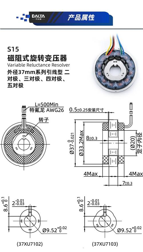
At present, there are two structural forms of transformers without brushing. One is called a ring transformer without brushing, and the other is referred to as a magnetic drag。
This structure is well achieved without brushing or contact. The right side of the figure is typical of the rotation transformer's fixation, rotor, which is structurally identical to that of the brushing transformer. The left side is the ring transformer. One of its circuits is on the dot, one on the rotor, and it's placed together。
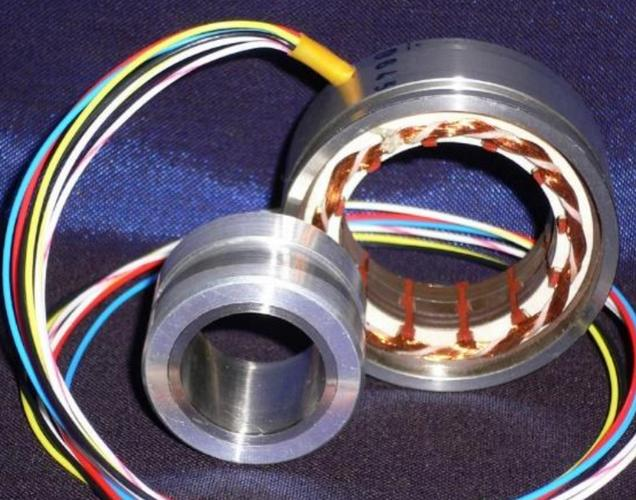
The ring transformer around the rotor is linked to the rotor around which the signal is converted, and its telecommunications output is done by the ring transformer。
Magnetic resistance rotate transformers have magnetic circuits and output circuits in the same set of slots, fixed. But magnetic and output bypass groups do not take the same form. The output signal of the two conjunctorted groups should still be a telecommunications number with a 90° difference in electron angles by the contour angle。
The rotor magnetic polar shape is specially designed to make the atmosphere field similar to the sine. The rotor shape must also be designed to meet the required threshold. As can be seen, the shape of the rotor determines the shape of the polar logarithmic and the chasm of the air gap。
Magnetic revolving transformers are typically assembled in compositions that are not grouped together and are provided to users in a sorting format, and are assembled by the users themselves。
Main parameters and performance indicators of the rotate transformer
Rotating transformers have a maximum of hourly induction voltage in their output circuit, with the rotor position being electrical zero and output voltage zero. Zero bit voltage is also known as residual voltage。
The ideal rotation transformer has zero bit voltage equal to zero. In practice, because of the presence of factors such as around-group misallocation, non-conformity of cross-axis, uneven magnetic conductivity of conductive materials, asymmetrical magnetic circuits, interference, etc., the rotation transformer's zero voltage is generally not zero, and the zero voltage is usually less than 0. 1 per cent of the maximum output voltage, and its base-wave voltage is usually larger, and accurate measurement of the zero voltage is an important component in evaluating the rotary transformer。
Phase shift is the phase difference between the magnetic voltage and the base mass of the output voltage. Rotating transformer phase shifts are usually ahead of schedule, and relatively fixed phase shifts are acceptable for the control system, but larger and unstable phase shifts are not permitted。
In general, phase shifts are reduced with the rise in base numbers and magnetic frequency. As temperature rises, around-group resistance increases, so does phase shifts。
In the control system, it is necessary in many cases to keep the phase shift or phase shift within a certain range。
The pressure ratio of the rotary transformer has the same meaning as that of the geostationary transformer, but when the rotater turns at different angles, the magnetic field is mixed to different degrees and the output voltage varies. Therefore, the transformer ratio is the ratio of the base weight of the maximum empty output voltage to the base mass of the magnetic voltage under prescribed magnetic conditions。
The above-mentioned characteristics of the rotary transformer present some difficulty in measuring its transformer ratio。
The transform ratio is the basic technical indicator for the rotation transformer and is generally labelled in the sign。
Among the technical indicators for rotating transformers, only two indicators, one for transformer ratios and the other for blockage of open entry, are generally indicated on the signboard。
Rotating transformers are usually blocked between 200 and 10 k times。
Linear error is the deviation of the actual output voltage from the theoretical output voltage when the linear rotation transformer remains at a rotor position in the working angle。
Where:
δ1 - linear error
Uranium' - the output voltage base wave fraction (similar to the maximum output voltage) measured at the rotor angle
Uranium - theoretical values for the output of voltage base wave fractions (similar to maximum output voltage) at rotor angles
U60 - theoretical values for the output of voltage base wave mass at 60°。
Electrical error means a deviation between the actual electrical angle of the rotor and the electrical angle obtained through output measurements. Not more than 12。
The original circuit group rotates the magnetic (relative circuit short circuits) and turns the rotor, measuring electrical errors at the theoretical angles of 0°, 90°, 180°, 270°, taking the algebras of these electrical errors as required, with the maximum absolute value being the cross-axis error。
Distinction between rotation transformer and encoder
The rotary transformer is a signal element that produces a voltage that changes with the rotor's corner. It is based on the electromagnetic induction principle, whereby the output signal achieves the phase transformation and range modulation of the input sine carrier signal, depending on the rotation transformer's rotor and fixed angle positions, and is ultimately handled by a dedicated signal or by certain dsp and single machines with functional interfaces, which interprets the angle relationship between the rotor and the indentation signal based on the range and phase of the output signal。
The typical rotation encoder uses a raster principle, using an pv method for angular location detection, which can be divided into incremental and absolute categories。
The main differences between rotary transformers and encoders are as follows:
1 the encoder more precisely uses a pulse count; the rotary transformer is not a pulse count, but a simulated volume feedback。
2. The encoder is mostly a square-wave output, and the rotary transformer is a positive cosine, which calculates the phase difference through the chip。
3. Rotating transformers have higher speeds and can reach tens of thousands, and encoders are less high。
4. The applied ambient temperature of the rotary transformer is -55°c to +155°c and the encoder is -10°c to +70°c。
5. Rotating transformers are generally incremental。
The fundamental difference between the two is the difference between a digital signal and a simulated sine or cosine signal。