
The electromagnetic transfer differential cipher speed system is essentially a magnetotransformation unit installed on a cage-type rotor aniso axis to control the current of the cillator's circuit through a transistor control device, changing the current, i. E. It can regulate the output velocity of the cipher。
The basic working principle of the electromagnetic transfer differential mixer is based on the electromagnetic induction principle. Figure 9. 1 shows a map of an electromagnetic ionator. As can be seen from the graph, the shifter consists mainly of both active and dynamic components. The active part is driven by cage-type rotors and rotates at constant speeds. It is a cylinder of iron and magnetic material, which is customarily called a power hub. The dynamic part is typically made to be similar to the direct-flow power grid, known as the magnetic pole. The magnetic pole is equipped with a magnetic bypass group, which is referred to as a sensor. The moving production machinery is connected to the sensor axis. The circuits are attached to the condensed circuits, which are connected by electric brushes and direct currents, and the active magnetic currents that flow around the convection are provided by direct current power sources. When magnetic circuits are connected by direct currents, the main magnetic circuits are created along the closed magnetic circuits, which form a closed circuit through the air — hub — gap — magnetic poles. As the power hub is dragged by the original motive and rotates in a constant direction, there is a relative motion between the power hub and the magnetic pole, with the power pole cutting off the magnetic field, thereby creating a sensory electric dynamic in the power hub, generating currents and creating a pulsed electro-centre reaction magnetic field, which produces electromagnetic power by synthesizing with the main magnetosphere. This electromagnetic electromagnetic rectangular will drive the magnetic poles in the direction of the power hub, which will rotate with the production machinery. The rationale for its speed system is illustrated in figure 1. As can be seen from the figure, the speed-reducing system consists mainly of transistor current power, electromagnetic transfer differentials and three major components. The current power supply of the transistor tube is usually a single-phase whole wave or bridge-type whole-flow circuit, which can easily change the size of the direct-flow output voltage by changing the control angle of the transistor。
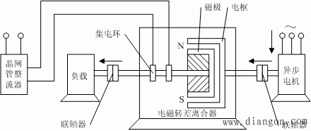
Figure 1 modular principles of the electromagnetic transfer differential mixer
Because the mechanical properties inherent in the arctic motor are hard, it is possible to assume that the rate of transmission of the power grid is almost constant, while the rate of rotation of the magnetic pole is determined by the strength and weakness of the magnetic field, i. E., by the current size provided to the electromagnetic ionator. Therefore, changing the size of the magnetic current can change the speed of the magnetic pole and of the work machinery。
Thus, when the magnetic current is equal to zero, the magnetic pole does not move, which is tantamount to a work machine being “leaved”. Once magnetic currents are added, the magnetic poles turn immediately, which is tantamount to a work machine being “closed”. That's where the clutch name came from. Also because it operates on the basis of the principle of electromagnetic induction, there must be a shift between the magnetic pole and the power hub in order to produce the sensory current and the electromagnetic rectangular, the full name is therefore referred to as the "electromagnetic transfer disconnector". It is often referred to as a “sliding power machine” along with its arcade motor。
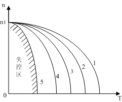
Figure 2 mechanical properties of electromagnetic transfer differentials at velocity
Because the mop is theoretically similar to the iso-motor motor, there is much similarity between the retrofitting properties of the magnetic current of the shifter and the retrograde properties of the iso-electric motor. Its ideal air-borne speed is an arcade, not a synchronized rate. In addition, when magnetic currents are over-hour, the magnetic field is too weak to produce very small rectangles, and the load will become unwieldy and run out of control, and therefore the mechanical properties are out of control. Its mechanical properties are shown in figure 2。
As can be seen from the figure, the mechanical properties of the electromagnetic transfer differentials mixer are soft, and in order to ensure a steady operation at the speed of rotation, the speed loop control is usually used, with a speed range of 10:1。
The main features of the electromagnetic transfer differentials velocity are simple control, reliable operation, no-grade velocity, improved speed performance with closed loop control and increased speed range; the disadvantage is that low speed losses are high and inefficient. This applies to situations that do not require low-speed operations over a long period of time. In addition, since the system has about twice the normal walker, the constant number of machine hours is such that it is not suitable for use in situations requiring a rapid response。
The mechanical properties of the electromagnetic transfer differential speeder system can be approximated by the following empirical formula:
Where
- the speed of the active part of the clutch
— coefficients associated with the structure of the clutch
- cracker
- magnetic current


