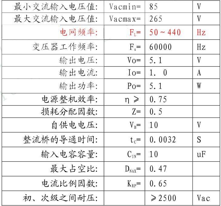
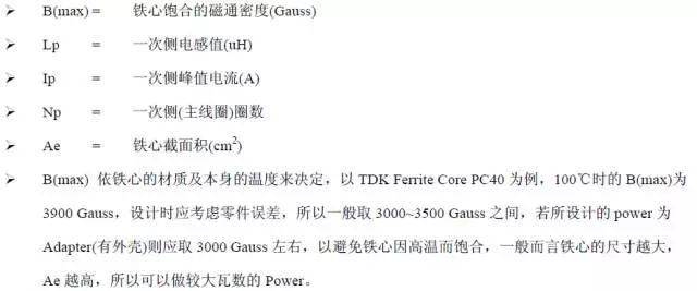
Power parameters
Depending on the power, input output, we choose to re-introduce。
The advantages of the reflector are:
1. The electrical circuits are simple and efficient in providing multiple straight-flow output and are therefore suitable for multiple output requirements。
2. Conversion efficiency and small losses。
3. The transformer has a smaller ratio。
4. The input voltage can still have a more stable output when it fluctuates in a large range。
Design steps:
1. Determination of power supply parameters。
2. Calculation of circuit parameters。
3. Select magnetic core material。
4. Select the shape and size of the magnetic core。
5. Calculate the number of transformers, the effective pyrophoric sensor coefficient and the length of the pyrotechnic。
6. Select the circle path。
Calculating transformer wear and tear。
Rationale
Step i. Determination of power supply parameters: (some parameters are given for indicators and some parameters are identified from information)
Note: the current ratio factor: the print rate, the print current and the actual current ratio in the case of heavy load and low income。
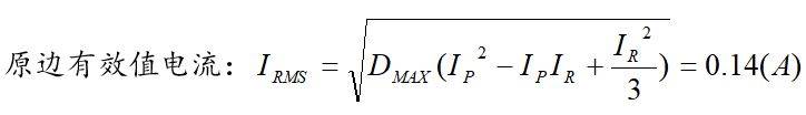
Step 2. Calculation of circuit parameters:
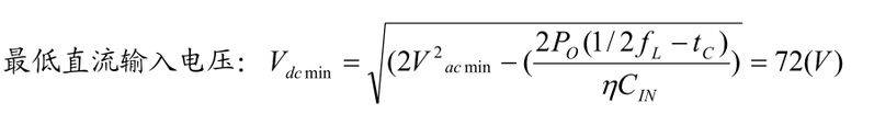
Minimum current input voltage:
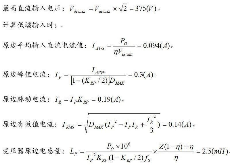
Z is the factor for allocating losses, if z=1. 0 indicates that all losses are on the side, if z=0 indicates that all losses are on the side, and here z= 0. 5 indicates that all losses are on the side。
Step 3. Select magnetic core material:
Iron oxygen material is characterized by high electrical resistance, low high frequency loss and a variety of materials and magnetic core specifications to meet requirements, combined with cheaper prices than other materials, which are currently the most widely applied in switch power. At the same time, there are the disadvantages of low saturation magnetic sensing, poor materials, intolerant shocks and poor temperature performance。
An initial magnetic conductivity of 2300 ±25%, a saturated magnetic flux density of 510 mt (25 °c)/390 mt (100 °c) and a cylindrical temperature of 215 °c were used for the use of power transformers for switches and for the transmission of high power units。
Select magnetic core material as iron oxygen, pc40。
Step 4. Select the shape and size of the magnetic core:
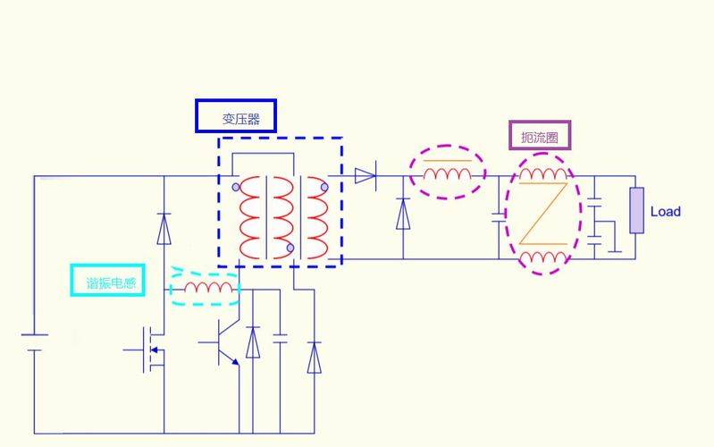
Magnetic material cannot be separated from high-frequency electrical circuits. Magnetic materials are used mainly in transformers, in the circuits, in the strangulation loops, including the resonance sensors。
The transformer is an important core of the entire power supply, so its calculation and validation is important。
Magnetic materials have a magnetic saturation problem. If the magnetic circuit is saturated, it results in the transfer of voltage transformer power, reduced electrons, etc. For power, the reduction in the amount of effective electrons will increase the amount of output texture, and the peak currents through the switch. This may result in a reduction in or damage to the life of the switch pipe by making it work beyond the safe working space. Another problem with magnetic material is the temperature of the inner point
(curie temperature) at this temperature, the magnetic properties of the material change dramatically. In particular, the material will change from a strong magnetic material to a magnetic material, i. E. A magnetic conductivity that will rapidly reduce several orders of magnitude. In fact, it's almost equivalent to air magnetic cores. Some ferrites can be down to 130oc. It is therefore important to pay attention to the working temperature of magnetic materials。
In short, two questions:
Saturation - causing loss of telemetry
Curry temperature - reduced magnetic conductivity
So when choosing the transformer, we need to consider two questions:
1. Magnetic fluxes must be satisfied to avoid saturation。
2. The temperature cannot be too high。
So we need to calculate the maximum magnetic flux of the iron-saturated heart of the transformer
To determine the material and size of the transformer:
Calculate formulas based on transformers
The b(max) calculation does not exceed the rating of the iron heart of our choice and reduces it and takes into account the effects of dissipation of the shell and leaves a surplus。
B(max) has two algorithms
Area multiplication (ap)
Geometric parameter method (kg)
The extrapolation process is complex and cumbersome and is not carried out here。
Here the magnetic core shape and dimensions of the transformer are selected using the area multiplier formula. Specific formulas are as follows:
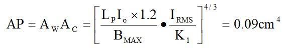
The anti-extreme transformer works at the first quadrant and the maximum magnet should remain residual, so the b = 0. 3t is selected and the coefficient for the anti-extreme transformer is k = 0. 0085 (k1 is the experience of the current density of 420a/cm in natural cooling)
Magnetic core type: chec magnetic core series - epc19, magnetic core parameters are:
Epc magnetic cores are primarily designed for flat transformers and have the characteristics of a medium column long and a low sense of leakage. Epc19 magnet cores have an ap value of approximately 0. 11 cm4, slightly greater than the ap=0. 09 cm4 required for calculation. If small number 1 magnet core efd15 is selected, its ap value is approximately 0. 047 cm4, less than the required ap = 0. 09 cm4 for calculation, and does not meet the requirements, the epc19 magnet core is selected。
Step five. Calculate the number of round groups of transformers, the effective zero sensor coefficient and the length of the gas gap:
1 faraday electromagnetic sensory law
The size of the electric motion in the circuit is proportional to the rate of magnetic fluxes through the circuit
Empirical orm law equation: v=l* (di/dt)
So the current-type equation was extrapolated:
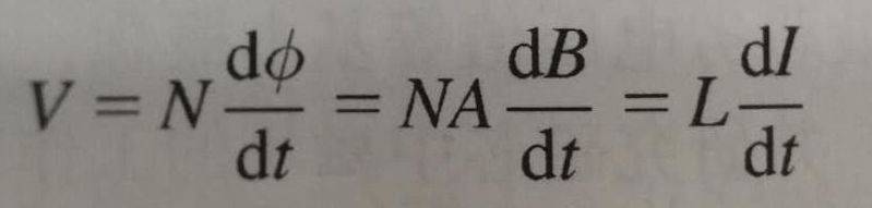
N*a*b=l*i
Number of original rounded groups:
Magnetic saturation density is determined when electrons, currents, zirconium, area are determined。
In other words, in order to achieve a certain level of magnetic saturation, we need to increase the numbers to achieve it。
When the numbers on the front side meet the requirements, we can calculate the sideline numbers through a round-up relationship。
Step vi. Select the route of the circuit route:
We also need to consider current and space issues while meeting magnetic fluxes。
The number of transformer lines and lines is determined:
When the transformer decides, bobbin (bones) of the transformer determines the current density of the transformer, which is generally based on 6a/mm2, based on the width of the tank of the transformer, and the diameter and number of lines of the transformer, which is based on a reference value only for the design of the transformer, which is ultimately based on a temperature increase record。
Bones width valid for transformer:
I'm the original quadrilateral layer, using 4 layers here。
M takes two millimeters for each end of the circle。
(crawling distance is the shortest route between two conductive parts measured along the insulation surface or between conductive parts and equipment protection interfaces. I'm not sure
Line width of skeleton: bw=11. 9 mm
Calculates the maximum diameter allowed by the original quadrant guide (paint wrap):
On the basis of the above calculation, it is possible to circumvent the paint pack line with a nudity dia = 0. 23 mm with a varnish diameter of 0. 27 mm, which can be bypassed on just four floors。
The current density of the original quadrant is calculated based on the selected thread:
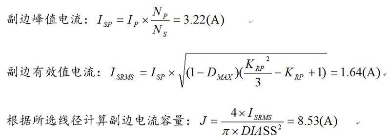
Calculates the maximum diameter (painted) allowed by the side bypass group guide:
Based on the above calculations, a paint pack line with a nud track diass = 0. 72 mm can be used to circumvent, but due to the skin depth of the copper line at 100°c working frequency of 60 khz:
By contrast, 0. 72 mm is more than twice the skin depth, which reduces the use of copper wires and therefore uses two 0. 35 mm paint-packing lines。
Self-electrical bypass circuits: since the self-electrical circuits are very small and have only 5 ma, the routing requirements are not very strict, and the main consideration here is to make it easier to connect with secondary and better mechanical strength, and therefore also to use a varnish line with a nudity diameter of 0. 35 mm, so that it is just one layer below, to reduce leakage from the subsector and to ensure a reduction in the self-electric voltage during short circuits。
Step 7. Calculating transformer depletion and temperature rises
The losses of transformers consist mainly of coil losses and magnetic core losses, calculated separately below:
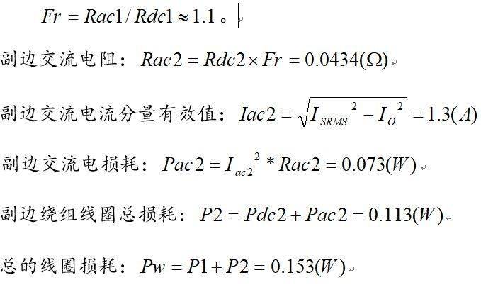
1) coil depletion:
A resistance rate of 2. 3 x 10⁻⁶ (cm) for 100 °c copper; a measured length of 360 cm for the original circle; and an area for the original 0. 23 mm paint line。
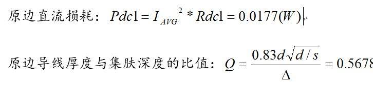
D the original line of paint is 0. 23 mm in diameter, and the centre of the line is 0. 27 mm and the skin depth 0. 31 mm。
(b) ratio of original exchange resistance to direct current resistance: since the original edge is rounded up, the original quadrilateral layer can be considered on two layers and found on the q value sought above。
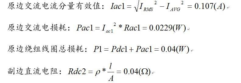
A resistance rate of 2. 3 x 10⁻⁶ (cm) for 100 °c copper, 80 cm for the length of the circle formed for the side, and an amplitude of two 0. 38 mm paint lines for the side。
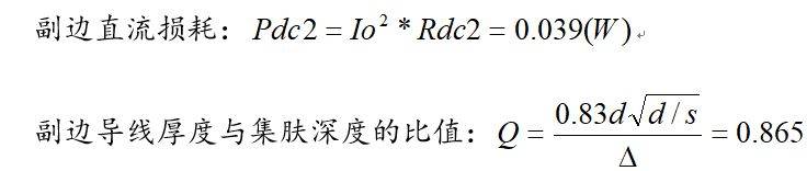
D 0. 35 mm in diameter for side-by-side paint packs and 0. 41 mm in centre of line and 0. 31 mm in skin depth. Secondary-side communication resistance versus direct-flow resistance: the number of side-by-side convection layers is one layer, and based on the q values sought in the above formula, the following are detected:
2) magnetic core losses:
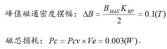
Pcv is the loss of magnetic core power, which can be detected in the manufacturer's manual by peak magnetic flux density banding, working frequency 60khz and working temperature 100°c。
Ve is 0. 105cm3 of epc19。
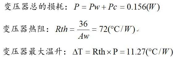
Summary: it is known from the above calculation that when ambient temperature is 85°c, the transformer's maximum temperature is around 96°c, which corresponds to the optimal working temperature of the magnetic core. The simultaneous use of rounding has resulted in a sense of omission of only 70uh (1khz time)/15uh (100 khz time), which is less than 3 per cent, which is more than desirable。