This invention deals with the field of precision engineering technology and is mainly concerned with visual measurements and the marking devices and methods of the light camera in the bias。
Background technology:
In modern precision measurements, deviation measurement is a optical high-precision measurement technique based on stripe reflection. Its main rationale is to obtain a geometric relationship between the point of view and the point of view using triangulation to obtain a geometric relationship between the point of view and the point of view, by projecting the ruler strip to the surface of the surface, deforming the strip by reflecting the surface of the surface of the surface of the surface of the surface of the surface to be measured, extracting the gradient distribution of the surface of the surface of the surface of the surface of the surface of the surface of the surface of the surface of the surface of the surface of the surface of the surface of the surface of the surface on the angle of the angle, and obtaining the height of the surface distribution by the fraction of the surface [. Zoe. Optical free curvatures based on monochromatic bias
Doctoral thesis of the university of jordan, 2019]. The advantages of such measurements, which are broad in scope, dynamic in scope, high resistance to interference, simple measurement equipment, low cost and non-contact measurements, have been of wide interest in recent years and are well used for large-calibre optical measurements and in situ online measurements。
The accuracy of the dichotomy measurement depends on the accuracy of the calculation of the input and reflection light. The traditional camera-marking method, however, is to obtain a physical match between the feature points using blocks with defined structure information, but the camera is described as a needle-hole imaging model, where the light passing through the pixel point is considered to be based on the ideal camera eye centre, the mathematical model of the object-point transformation is created by means of triangulation, etc., and the parameters of the camera model are derived from the image-point correspondence and the direction of the light. Wengj, cohenp, hernioumNmoddel (ccdsensorry)
10thinternational conferenceconferencenrecognition. Ieee, 1990: 246-253), traditional camera model solver usually has a two-step approach to tasi.[tsair. Versatilecameracaliberationtechniqueforgh-accuracy3dmainvisiontechnologyusingoff-the-shelftcamerasandlens]
. Ieeejournalonroboticsautomation, 1987, 3(4): 323-344], zhang zhengthou (zhangz. Aflexiblenewtechniqueforcameracallation)
. Eeetransactionsonatternalysmachineintelligence, 2000, 22 (11): 1330-1334, etc。
However, the light in the actual camera camera is of a certain size and, as a result, it produces a difference. The location and direction of the light obtained is biased, which affects the accuracy of the measurements. It is therefore necessary to optimize the model for this camera to improve the accuracy of the camera。
Technical realization elements:
In response to the inadequacy of existing technology, the technical problem to be addressed by this invention is the provision of a camera calibration method for optical face measurements, which increases the calibration accuracy of the camera, thus increasing the accuracy of the optical face measurements by aberration。
The method of calibration of the light camera, which is used for optical face measurements, is set on the guidance track, and the panel containing circular features can be moved along the course, as the method in question includes the following steps:
(b) photos of the corresponding positions at focus positions and at a number of back and back symmetry
(a) a linear interpolation by a triangulation method to indicate the eye coordinate of the other image characterization points, using the light coordinate of the feature points on the image at focus position
Constructing the equation between the pixel point and the actual object coordinates by imitation and teratogenic transformation of the object by deciphering the matrix parameters
The best solution is obtained by a very seemingly reduced projection error, thus obtaining light direction。
This paper uses a tablet test device with a smoother pattern, with the camera and the plate vertically attached to the test table, and the dot panel attached to the guide, which is parallel to the camera light axis. The camera position, the number of lenses and the focal length are always fixed, the initial position of the plate is in the best clear image view, the parallel movement of the panel in the camera depth area through the guide tracks, using the pupil offset (a0, b0) of the image feature point of the most clearly imaging location as the base point, and the light coordinate (a0, b0) of the other image feature points is used (a0, b0) to decipher the parameters through the odd-occult division. Each of the marked light is marked with its respective pupil position offset. All light in this invention breakhole model must go through the same radiance limits, break the traditional needlehole model limits and improve camera marking accuracy。
Annex figure description
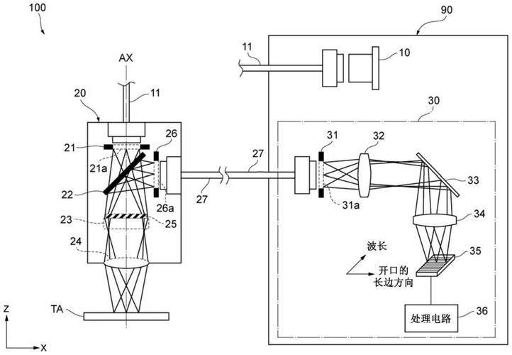
Figure 1 - figure 2 shows the structure of the plant that was marked by this invention。
Figure 3 shows the flowchart of the process of marking this invention。
Figure 4 shows the image of the plate obtained。
Figure 5 shows a re-scan error rms for the method of flattening the plate。
Implementation modalities
This invention is further elaborated in conjunction with the accompanying chart and the implementing examples。
As shown in figure 1 and figure 2 below, the structure diagram of the device marked for this invention shows the experimental device routing, the camera being a light camera, and the image taken after the parallel moving panel, as shown in figure 4; figure 3 shows the flow chart of the process for marking this invention, including the following steps:
Step 1, control the camera optical circle and calculate the depth of the scene, and place the pallet in the most visible image
Step 2, move the palette and take the images, keep the panel images clear and record the distance of movement
(b) step 3, using as a base point the eye coordinates of the feature points on the image at the most clear imaging point, to indicate the eye coordinates of the other image feature points
Step 4, yielding matrix parameters for the transformation of the image through odd-indicator decomposition
Step 5, obtaining optimal resolution through a much more semblance of estimation to reduce the error in the re-projection, thus obtaining light direction. In accordance with the methodology proposed in this invention, the physical location of the site is compared with the location of the post-solver site of the model, with the distribution of the re-projecting error as shown in figure 5. It can be demonstrated that the re-projecting of rms in 0. 04 pixels of this method achieves very high accuracy。
The device and method of calibration of the light camera, which was invented, does not limit the passing of all light through the same light heart, breaks the pinhole camera model by establishing the light coordinate system, and specifically, the method of calibration of the camera for optical face measurements, which was invented, includes the following elements and implementation steps:
1) the construction of the camera marking system, including the camera to be marked, the panel with circular features, and the high precision guidance track, which fixes the panel to the guidance track and adjusts it to the best clear image position and records the imaging at this time. It then moves parallel panels, moving back and forth at a depth of 1/2 (or at a depth of 1/3 and at a depth of 2/3 and below, for example, at a depth of 1/2) and records movement distance and separate images of the corresponding position. In fact, a number of positions can be symmetrically moved before and after the focus position, only to ensure that they remain as far away as possible
2) builds a mathematical model between camera pixels and feature points, with the characterization point world coordinates j indicating the panel position number, j =-10,1 of which position 0 indicates the best focus position, position 1 indicates a forward move of 1/2 view and position 1 indicates a backward move of 1/2 view. I means a feature point number with a cross-n feature point whose pixel point coordinates on the image are used to construct the equation group based on the coordinates of the acquired physical point:
Of these, zc represents the x-coordinate of the camera face and tj the z-direction deviation at j of the plate position. It indicates the x-direction deviation of the main light caused by different light coordinates and the y-direction deviation of the i feature point at location j。
3) the above offsets are represented by the offset plug in the base position. Using the image at position 0 as a benchmark, the pixel coordinates of all spots form the trigonometric grid, and the pixel coordinates of other images are inserted on the trigonometric grid, indicating the linear combination used for the corresponding deviation:
Of these, the factor is determined。
4) dj indicates the distance of the palette from position 0 to j, which is available:
The entry (3) of the coordinate data obtained from each feature point and the corresponding pixel coordinate data to the new equation group can be replaced by the equation (2) because both are expressed and both are expressed group
Parameters (m11, m12, m13, m21, m22, m23, m31, m32, m33) are deciphered by odd altimeters. As the equation is inexhaustible, it is scaled to the right factor, resulting in zc = 1
5) by means of a very specious method of estimation, a joint k-band is created to map the coordinates of the first i feature point on the j-spectrum, which represent the points of correspondence derived from the light trace using the above-mentioned camera model, as the actual points of image。
Using the levenberg-marquardt method to obtain the best solution, the bottom line is minimal。
The measurement system was constructed using the method of this invention. The camera is manufactured by jai company and is of the type sp-2000c-pmcl, with a focal length of 50 mm and a f number of 11, with the camera body approximately 400 mm from the plate, with a pixel point size of 6. 4 m x 6. 4 mm, and the camera, the plate, is approximately at a vertical level, at a depth of approximately 50 mm. Due to the unknown amount of 9 m arrays in the equation group, there is an unknown amount of tj square in each of the 2n pupils. One image provides 2n equations, and if only two images are taken, at least six feature points are required, and if more than three images are taken, at least three. The actual number of dots selected for the dot is 42 x 41 and the diameter of the dot is 3 mm。
The location of the camera body, the lens focal length and the number of optical circles are then fixed, and the plate position is adjusted so that it is as clear as possible to record the image at this time. The tablet is then smoothed, the image is kept clear throughout the session, moving back and forth at a distance of 20 mm, and the corresponding position images are recorded separately。
This invention has the following advantages compared to existing technologies:
The invention overcomes the traditional pinhole camera model by default that all light is subject to the same pupil limit, by setting each marked light with its own pupil deflection, and by smoothing the palletation method to resolve the image change matrix and the pupil deflection, breaking the model limitation, increasing the accuracy of the mark, reducing the number of images taken and effectively improving the efficiency of the marking。