Knowledge point: generator circuits
Generator working principles
The vehicle's power supply consists of a combination of a vehicle generator (figure 1) and a battery, which provides electrical power to the vehicle's electrical appliances in the event of engine outburst, while at the time of start-up the vehicle provides electrical power for the motor. When the engine is activated, the generator is driven to power. Generators are charged to the battery during the power generation and the whole vehicle is supplied。
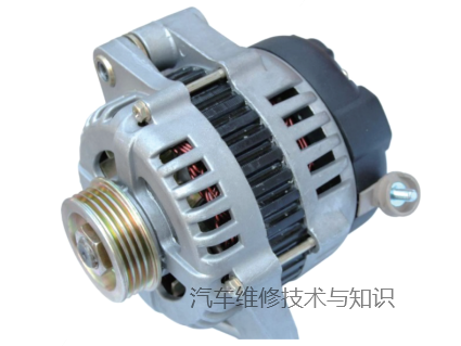
Figure 1: generators in kind
The vehicle generator is a three-way exchange generator and the electricity is a three-way exchange. So how do generators generate electricity? How did the three-way exchange turn into a straight current? The generators consist of several key components, such as beams, rotors and whole-stream bridges. The dots and rotors are wiring and the whole flow bridge is controlled by the silicon diode. As shown in figure 2, powering the rotor creates a magnetic field. At this point, if the generator's rotor rotates with the engine, the magnetic field is a rotating magnetic field. Its counterpart, installed outside the rotor, is a ring consisting of three circuits, which staggered each other 120°, and three loops, which are triangulated to produce three nodes. When the rotor rotates, the three dots of the ring can sense a communicative electricity with a 120-degree difference. This communication, which passed through the bridge, turned into a direct 14v power supply to the whole vehicle。
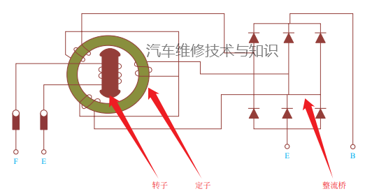
Figure 2: generator working principles
The generator's rotors rotate with the engine, the higher the engine's speed, the higher the generator's output voltage, the lower the engine's speed, the lower the generator's output voltage. But we need generators to always export a stable 14v voltage. That would require a device to adjust the output voltage. How do you adjust the voltage? You just have to adjust the magnetic current of the rotor. The device that adjusts the output voltage to the magnetic current is called the voltage controler, which is divided into built-in and external regulators according to the location of the installation. It is now almost impossible to see an external modem in the car, so it is not introduced. The built-in voltage regulator is installed in the back of the generator, as shown in figure 3. The voltage regulater had two charcoal brushes, which were pressed directly on the rotor to provide magnetic currents to the rotor. The power supply of the voltage regulator varies according to the vehicle-type circuit structure, looking specifically at the generator-type logic of circuit control。
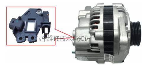
Figure 3: internal voltage regulators in kind
Five control logic and frequent failure overhauls
A. Control logic
Figure 4 shows the generator circuit in the light of mitsubishi. There are only two lines on the generator: one is a b+ line, which is an output line for the generator; and one l line, which is defined as a generator signal light, which is basically the same for all generators, and the other end of the l line is connected to the instrument. The sign inside the instrument is connected to the positive end and to the l end of the generator. If the l end is negative if no power is generated, the battery signal light is activated; if the generator is powered, the end is positive and the battery signal light is extinguished. Such generators control circuits are referred to as self-reactive control circuits. The revolving magnets were derived from the b+ endpoint of the engine, so whether the generator generated the power was not related to the l end。
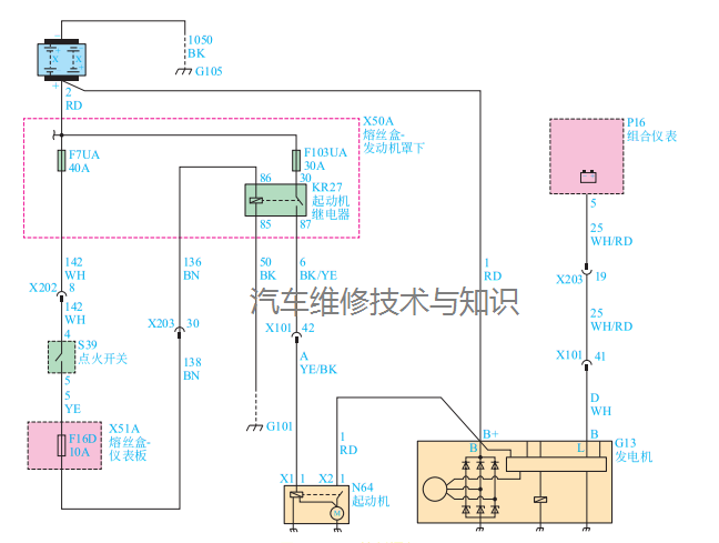
Figure 4: a control logic
B. Control logic
Figure 5 shows the generator circuit of haft h6. Three lines can be seen at the end of the generator: the b+ line is the generator's output line; the l line remains the signal light control line; the ignition switch turns on the ig line for electricity and the ig line is also called the f-magnetic line in some models. Generators using this control method are also referred to as regenerative generators。
In repairing the failure of such generators to generate electricity, care needs to be taken as to whether the voltage of the ig ends is normal. Without the voltage, the generator loses its magnetism and does not generate electricity。
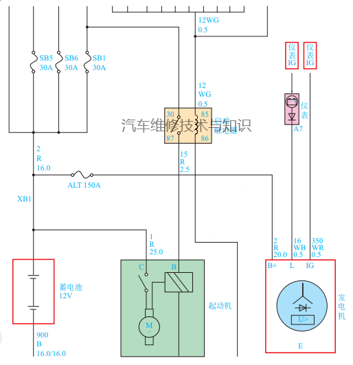
Figure 5: b control logic
C. Control logic
Figure 6 shows a popular generator circuit with three endpoints, b+ and t2ax, respectively. Similarly, the b+ line must be the generator's output line. A wire to an engine computer, known as the dfm line, is a line where generators report their loads to the engine computer through an empty ratio signal. If necessary, the engine computer increases the engine speed. The other computer that goes to the body computer is the battery signal line, which determines whether the current generator is working at the voltage of the battery signal line and, if the voltage is too low, cuts some of the heavy load electrical appliances on the vehicle in due course。
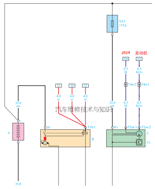
Figure 6: c control logic
D control logic
Figure 7 shows the charging system circuit in koruz, which consists of a battery current sensor, a body computer (the body control module), an engine computer (the engine control module) and a generator as a power management system. The system enables the output voltage of generators to be adjusted in real time to the current load status of the vehicle-borne grid. At the same time, the power management system will perform the following three functions: monitor battery voltage and estimate the condition of the battery; correct action by increasing the speed of glide and regulating stable voltage; and diagnose and alert drivers。
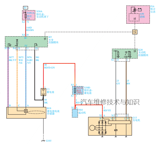
Figure 7: d control logic
The components of the recharge system function as follows:
Generators:
It's a repairable part. If the generator is diagnosed with failure, it must be replaced as a total. Engines drive the belt-driven generators. When the rotor rotates, it will generate exchange power (ac) from the integer circuit, which will be converted to direct current power (dc) through a series of diapole currents for use in vehicle electrical systems to maintain electrical load power and battery charge. The voltage regulator is integrated with the generator control unit, which controls the generator's output. It can't be repaired. The voltage regulator controls the flow of the rotor supply. If the generator's magnetic field controls circuit failure, the generator's default output voltage is 13. 8 v。
Body control module (bcm):
It's a gmlan device. It communicates with the engine control module (ecm) and dashboard combination instrument (ipc) for power management (epm) operations. The body control module determines the generator output and sends information to the engine control module to control the generator's access to the communications circuit. It monitors information on the spatially proportional signal circuits of the generator magnetic field from the engine control module to control the generators. It monitors the battery current sensor, the cell is a polar voltage circuit, and estimates the temperature of the battery to determine its recharge status (soc). The body control module has been downped. Battery current sensor. It is a removable component that connects the battery to the battery's negative polar cable. The battery current sensor is a three-line hale current sensor. Battery current sensors monitor battery currents. It is entered directly into the body control module. It produces a pwm signal of 128 hz, with a zero-100% space ratio. Normal space ratio is between 5% and 95%. The gap between 0-5% and 95% and 100% is used for diagnostic purposes。
Engine control module (ecm):
When the engine is running, the engine control module sends the generator to the generator for communications to open the regulator. The generator voltage regulator controls the output voltage by controlling the current of the rotor. The rotor current is proportional to the pulse width provided by the regulator. When the engine is activated, the regulator detects the rotation of the generator by detecting the exchange voltage on the in-house guide. Once the engine is running, the regulator changes the magnetic current by controlling the pulse width. This will regulate the output voltage of generators, allow the battery to be recharged and the electrical system to function. The generator's magnetic field is connected internally to the voltage regulator and externally to the engine control module. When the voltage regulator detects a failure of the recharge system, it will use the iron circuit to notify the engine control module of a failure. The engine control module monitors the generator's magnetic field as a ratio signal circuit and receives control instructions based on body control module information。
Summary:
This control logic is applied to many models, mainly to motor computers or body computers, which adjust generator power (space ratio) to current vehicle capacity, while generators also provide a signal to engine computers or body computers to inform them of their current load status。
E control logic
Figure 8 shows the generator circuits of the bmw 3 system, which are used in many high-end generator-control circuits. The control logic is not very different from that of koruz, except that the line that actually controls the engine has been changed to the lin bus, called bsd bus in the bmw model, which is actually the control of the lin bus. When the generator loses communication with the engine computer, the generator's voltage cannot be changed by following the vehicle's load and will be generated by a fixed voltage. If the generator fails, it can be repaired as a communication type failure。