Vt-vspa1-11 rsf scale magnifier, vwabac supply product, original plant, quality assurance, false ten-year penalty, and new and old clients are welcome to consult
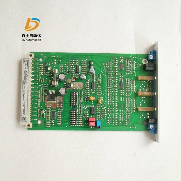
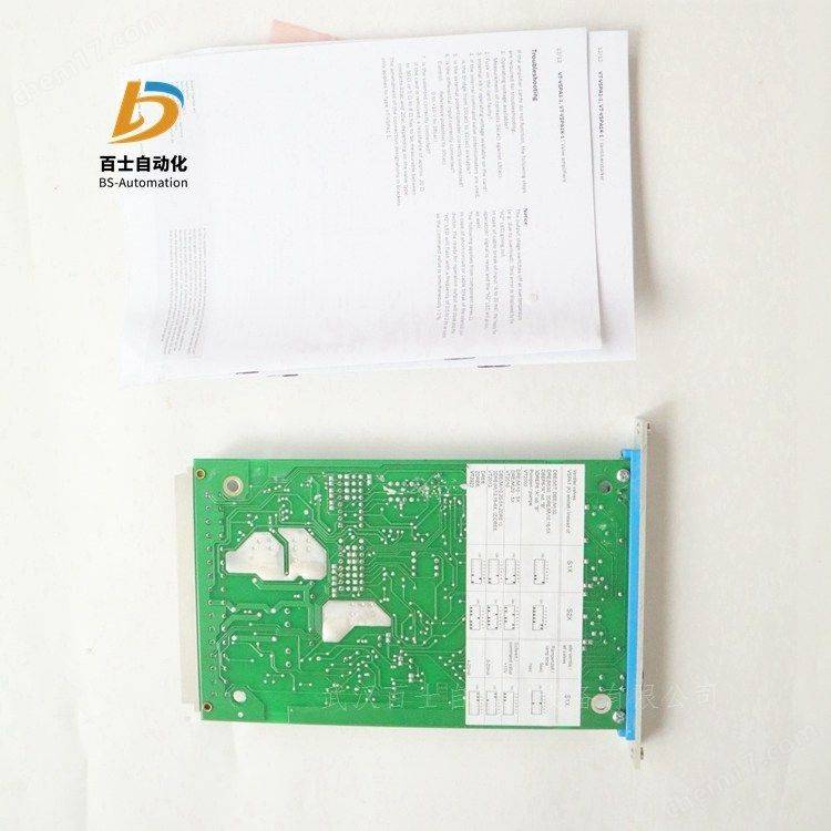
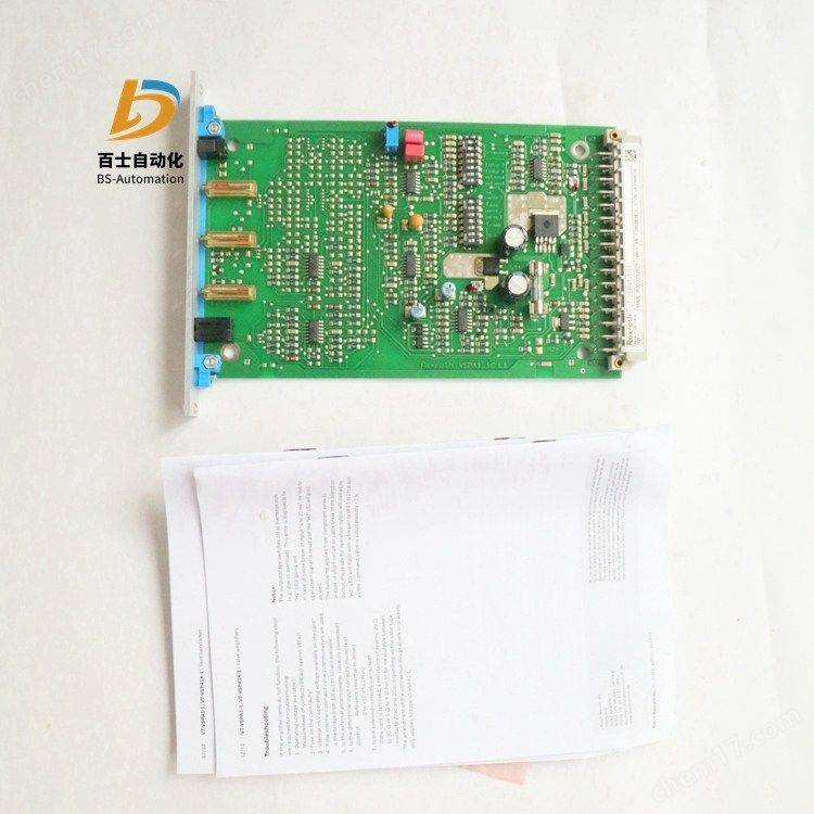
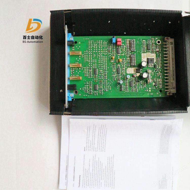
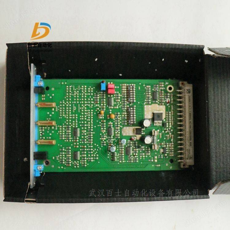
Rexroth for proportional pressure valves and proportional flow control valves amplified device
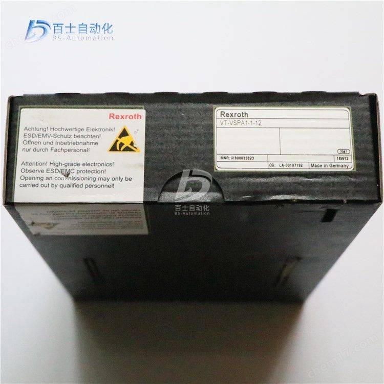
Vt-vspa1(k)-1-1x
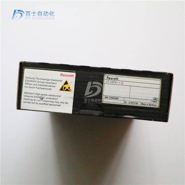
R90033823 vt-vspa1-11
R90033823 vt-vspa1-12
R901152637 vt-vspa1-11-10/v0/0
Component series 1x
Simulation, european card format
Applicable valves:
Dbep 6 (a/b) 1x
Dbe(m) 10 5x, dbe(m) 20 5x, dbe(m) 30 3x
Dbe 6. 1x
Dre(m) 10 5x, dre(m) 25 5x
Dre(m) 32 4x
Zdre 10 vp 1x
Difference input, switch from voltage input to current input
Additional control values entered 0 to +9 v
Slipper generator, adjusted for up and down, respectively
Time power output level
Ready message (with vt-vspa1k-1 model shown in led)
Inverse polar protection of power
Cable interrupt detection for current input from 4 to 20 ma
Short-circuit protection of the coil guide
Cable outage detection on the wire
The +9 v regulation of the voltage by power supply equipment can control the controlled voltage at input 1 directly or through an external control value bit count。
Structure and classification of hydraulic control valves
It's divided into slide valves, nozzle valves, and flow-pipe valves
1 slide valve
Advantages: high power, high magnification factor, high manipulation, low sensitivity and processing difficulties。
Is often used in front grade。
Side: four sides, bilateral, unilateral
Through: four and three channels for the slide valve
Opening type: the size of the core convection relative to the width of the valve tank at zero
The server valves are usually open or open mostly, while the electron ratio valves are generally negative。
2. Nozzle block valve
Advantages: no friction, high sensitivity, speed of response, low control power required
Disadvantages: pollibility bad
It applies to small power and is often used for front-level magnification。
It is controlled by type b hydraulic semi-bridge and consists of fixed throttle boreholes plus variable throttle vents。
Classification: single nozzle and double nozzle valves valve
The former are simple in structure but can only be used in conjunction with asymmetric tanks and have asymmetrical properties
The latter characteristic symmetry, which is primarily used to control symmetric execution components
3. Plumbing valves
Composed of flexible flow tubes and receivers. When the flow tube is swinging, the dynamic energy on the receiving side and the right side of the receiver varies, leading to different pressures for conversion and the control of hydraulic power。
The manoeuvring of the current tube is generally more powerful than the shield, but the current valve is better resistant to pollution. The range of applications is not as wide as the nozzle valve。
In the case of slide valves, the static properties of valves, the principles involved and the method of export applied to hydraulic control valves of various structures。
Static:
The function relationship between the valve's load flow 2r, load pressure pl and valve shift xv when the valve is stable, i. E. 2 = f (xv, pl)
It reflects the capacity and performance of the valve itself。
The static properties of the valves can be obtained either by resolution or experimental methods. The general experimental method is more accurate
However, the resolution is easy to predict the characteristics of the valve。
The static properties can be expressed in the characteristic equation, the characteristic curve and the characteristic coefficient (valve factor)。
Valve coefficients can be obtained from a special equation or a characteristic curve, which refers to the incremental variation of the valve at the given work point。
Hydraulic ratio control system
The power and motion direction control is performed by proportional control components, divided into proportional pressure valves, proportional flow valves, proportional direction valves and proportional direction flow valves, which can be entered for simulations or numerical volumes, with or without feedback divided into open and closed loop controls, and generally not within a high frequency (10hz), with a high frequency being achieved。
If precision requirements are low, the electron ratio control system may be considered, and the general electron ratio control system may reach the following accuracy:
Location precision - 3 mm
Speed precision with pressure compensator - 3%
Plus deceleration slope time - 0. 5 seconds
The product-scale pressure valve is 0. 3% (up to 0. 6 bar if pressure is set at 200 bar)
Common multi-drive hydraulic systems require flow and pressure control to provide proportional pressure and flow control systems
Open-ring proportional pressure and flow control can be used for quantitative and variable pumping systems。
Speed and flow ratio controls are:
(a) traffic control only controls the supply of oil and does not control the direction of the driving elements;
A speed control system is used when the system loads and speeds are high。
Speed ratio control is used mostly for automated controls, retrofitters, pressurers, etc
Main reasons for the use of closed rings:
Maintaining set values free from external interference
Keep it steady under different work pressures
It's the same position under different output forces
Synchronize movement while overloading
Increased precision requirements
Location error below 1 mm
Pressure error below 1 b
We need to control the rate of increase and decrease
Systems with high dynamic requirements
Simulation application
Test application
Hydraulic server control system
The power and movement direction control is performed by the server control element, combining pressure, flow, direction control, correction using deviation control to meet precision control needs, which must be controlled in closed loops, with a higher frequency (100 hz or more), with slide valves, nozzles, flow tubes, etc., often using mechanical, electron and gas-serving。
Hydraulic server system classification:
(1) categorized by the pattern of signal changes entered: the fixed value control system, the programme control system and the server system. When a system input signal is a fixed value, it is referred to as the fixed value control system, whose basic task is to increase the system's resistance to interference. When the system's input signal changes according to a pre-determined pattern, it is called the program control system. The server system is also referred to as a live system, and the input signal is an unknown function of time, and the output can accurately and quickly repeat the pattern of input changes。
(2) different categories by type of input signal: machine fluid server system, electron server system, gas server system, etc。
(3) classification by physical quantity of output: location server system, speed server system, force (or pressure) server system, etc。
(4) classification by control element: valve and pump control systems. In mechanical equipment, valve control systems are more applied。
Zoom in on the vt-vspa1-11 resler board
Rexroth simulation circuit magnification, european layout
A valve amplifier for the rexroth ratio to the valve and the proportional pressure valve
0811405081 vt-vspa1-508-10/v0/rtp
Vt-vspa1-525-10/v0/rtp
R901152628 vt-vspa1-10-1x/v0/0
R901152637 vt-vspa1-11-1x/v0/0
R901362646 vt-vspa1-11-1x=v0/0
R90033823 vt-vspa1-1x/
R900916996 vt-vspa1-1-x/001
R90934744 vt-vspa1-1x/002/60sec
R900900278 vt-vspa1-1x/003/4-20ma/450ma
R900966500 vt-vspa1-1-x/004
R90978827 vt-vspa1-1-x/005
R978911748 vt-vspa1-1x/es43a8-1707
R978916539 vt-vspa1-1-x/es43a8-3564/a2, a3
R978918946 vt-vspa1-1x/s043a-1609
R978918205 vt-vspa1-1-1x/so43a-1616
R978919118 vt-vspa1-1-x/so43a-1729
R9000053778 vt-vspa1k-1-1x/
R97891478 vt-vspa1k-1-1x/so43a-1668
R978839687 vt-vspa1k-1-1x/so43a-560-1
R90934739 vt-vspa1k-1-x/002/15sec
R90934741 vt-vspa1k-1-x/002/60sec
R90072310 vt-vspa1-2-1x/v0/0
R901002761 vt-vspa1-1x/v0/a4
R901356608 vt-vspa1-2-1x = v0/0
R901002090 vt-vspa2-1-2x/v0/t1
R901002095 vt-vspa2-1-2x/v0/t5
R901356606 vt-vspa2-1-2x = v0/t1
R90033828 vt2000-5x/
Lead pressure reduction valves
1. Structure and rationale:
When the valve is not working, the valve is open and the oil can flow through the main valve core from mouth b to mouth a. While the dr10 establishes pressure in the valves, the pressure oils act through a detoxifier to control the passage to the upper end of the main valve core and the cone valve of the lead valve. The cone valve is opened when the valve pressure exceeds the adjusted pressure of the spring. At this point, oil from the upper cavity of the main valve flowed to the spring cavity through a detoxer, thus creating a pressure differential on the cavity of the main valve, in which case the main cavity moved and the opening was reduced to keep the a cavity pressure constant. Controls the flow of oil through channels or from outside discharges to tanks. If a one-way valve structure is selected, the oil may flow from the a cavity to the b cavity。
The dr20s and dr30s work in the same way as the dr10 valves, but control the oil from the channel
Introduced and equipped with a flow-restrictive constant in the lead valve。
When q = 0 flows, the overload valve (10) can limit the height of the a cavity pressure and ensure that the valve is not destroyed。
Zdr direct motion reduction valves are superimposed valves. It is a three-valve, i. E. A valve with a secondary circuit offloader. It is primarily used to reduce pressure on some systems。
The valve consists mainly of valves, control valve cores, two pressure springs, pressure regulation devices and optional one-way valves。
The secondary pressure is regulated by a reconciliation device。
The valves are open, meaning that the oil can flow smoothly from channel p to p1 (dp type) or from a to a1 (da type)。
The pressure oil of the p1 cavity flows through the control channel to the left of the core of the valve, pressing it on the spring. When the pressure of the p1 cavity (i. E. Load) exceeds the adjusted spring adjustment value, the core moves within the regulated area
Move to keep pressure constant on its p1 cavity。
Control oil was introduced from the p1 cavity channel. The pressure of the p1 cavity continues to rise because of the effect of the external load, which results in the pressure oil passing through the hole in the valve core (flowing to the t1 cavity (offloading), and thus overload protection。
The spill was discharged to the tank through spring cavity (7)。
"da" can choose a one-way valve with oil flowing back from the a1 cavity。
A pressure sheet is installed at the interface to detect secondary pressure values。
Zdr, d-type pressure-relief valves are stacked pressure-relief valves. It is a three-valve, a valve with a secondary circuit protection device. The valve is primarily used to reduce system pressure。
The valve consists mainly of valves, control cores, two pressure springs, pressure regulation devices and one-way valves of choice。
Rotation pressure adjusters regulate secondary pressure。
The valve is open at stationary time, meaning that the oil can flow smoothly from channel p to channel p1 (dp) from a to a1 (da) and from b to b1 (db). The pressure oil of the p1 cavity flows through the control channel to the left side of the core of the valve, which causes the total pressure of the valve to spring. When the pressure of the p1 cavity (i. E. Load) exceeds the adjustment value of the regulated spring, the core moves within the regulated area to maintain the persistence of its p1 cavity pressure。
Control oil was introduced from the p1 cavity channel (5). The pressure of the p1 cavity is sustained by the external load
Up, push the core compressed spring so that the pressure oil flows through the hole in the valve core (7) to the t cavity pressure no longer. Litres
High, thus achieving overload protection。
The oil spill was discharged to the tank through spring cavity (8). "da" and db-type pressure-relief valves, to install orders
To the valve, the oil can flow from a1 to a and b1 to b. Secondary pressure can be measured at pressure table connector (9)
Value。
2. Common malfunctions and removal of pressure reduction valves.
Common malfunctions of the pressure reduction valves include pressure failure, pressure on the core diameter of the valve, self-imposed increase in the pressure of the oil vent as a result of working pressure adjustments, noise, pressure fluctuations and oscillation。
(i) decompression failure
The following are some of the symptoms of the breakdown:
The pressure on the throttle is not rising. One of the reasons for this is that the main valve core obstructs the cavity of the cavity, the cavity of the cavity and the cavity of the cavity of the cavity of the cavity, and the pressure of the cavity does not pass on the cavity of the cavity of the cavity, thereby depriving the cavity of the function of regulating the cavity pressure of the cadaver. The main valve was also shut down when the pressure of the vent was very low, resulting in the loss of pressure p3 from the upper cavity of the main valve and the transformation of the main valve into a low-strength straight-flip valve. In addition, when the main valve reduces the pressure level of the valve, the fact that the main valve core is stuck, the cone valve is not installed in the hole of the valve and the external controls are not blocked, etc., is the reason why pressure on the vent cannot rise。
The pressure on the outlet is not up to a rated value, owing to, among other things, the error in the spring adjustment, insufficient deformation or compression of the process, and excessive wear and tear of the cone valve。
The pressure from the throttle and the pressure from the vent rises or decreases simultaneously, as a result of the congestion of the cone valves, the congestion of the blockers, the blocking of the vents and the leakage of the one-way valves。
The cone valve is blocked by a small hole, and when the blocker is blocked, the pressure from the vent is no longer transmitted to the cone
On the valve, the conductor loses control over the pressure of the main valve from the oil vent. The pressure of the oil mouth changes as the main valve and lower cavity fluid pressure is equal, with the main valve core at the lower end of its position as the main valve spring force and the reduced vent flow area is large, as a result of blockage of the small hole。
If the oil vent is blocked, it is theoretically equivalent to a cone valve blocking a small hole, which is blocked by a blocker. The pressure of the vent then works on the cone valve, but there is also no lead flow through the main valve core blocker, the decompressor blocker, and the area of the vent flow is also large, so the pressure of the vent also changes with the pressure of the entering mouth。
When the one-way reduction valve is leaking heavily in the one-way portion of the valve, the inflow pressure is passed through the leak to give the oil mouth, which also changes with the pressure of the inlet. In addition, when the main valve decompression vent is fully open, the pressure of the main valve is subject to changes in the pressure of the vent as the main valve core is stuck。
The pressure on the vents does not decrease when the wheel is regulated. This is mainly due to the holding of the main valve core. The reason for the export pressure does not reach the low-key pressure is mainly due to the tightness of the "o" seal and valve cap in the lead valve。
(ii) thrust of valve core diameter
Since the main valve spring of the pressure-relief valve and the one-way pressure-relief valve is weak, the main valve core is vulnerable to rudder-tightness at high pressure, and the reduced performance of the valve will cause excessive wear and tear of the parts and reduce the useful life of the valve and even render the valve inoperable and must be eliminated。
(iii) self-repressure of oil vents when working pressure is adjusted
In some pressure-reducing circuits, such as those used to control the fluid switch valve or the external control sequence valve, the flow from the pressure-reducing valve to the vent is zero when the electron switch to the valve or the external control sequence valve is switched to or worked, provided that the pressure is maintained as previously adjusted. In such cases, the pressure on the vents of the pressure reduction valves tends to rise, due to excessive leaks from the main valves。
In this working situation, as the flow of the pressure-reducing valve has turned to zero, the flow of the flow through the pressure-reducing vents is only a lead, which is essentially at the full level because the lead flow is small, usually within 2 litres/mins, and the lead flow is flowing from the trigonometry or slopes. If the main valve core is too loose or worn out, leakage from the main valve increases. By the inference of continuity of flow, this part of the leakage must also flow from the main valve to and from nicone, i. E., the original lead flow and two parts of the leakage. In order to increase the flow of anti-nicoholes, the pressure of the cavity fluids under the main valve is bound to rise to p2 due to the unchanged area of the barrier and the pressure of the cavity fluids above the main valve (p3 is determined by pre-compression of the adjusted pressure spring). Thus, when pressure reduction valves are adjusted, when the export flow is zero, the export pressure rises because the main valve core is too loose or worn out。
(iv) noise, pressure fluctuations and vibrations
Since the pressure reduction valve is a pilot two-stage valve, the conductor portion of the valve and that of the spill valve are partly common, the cause of noise and pressure fluctuations is essentially the same as that of the spill valve. The pressure-reducing valves are used in overflows, sometimes with main valve oscillations, causing constant pressure on oil outlets. Land litres
A one-litre charge and a one-litre charge are due to increased fluid flow due to innumerable flow. When the flow is too large, the weak main valve spring does not balance the increase in fluid flow caused by the excess flow, so the main valve core shuts down the pressure vent as a result of the fluid flow, and the pressure and flow of the vent is zero, so that the main valve core opens the pressure vent as a result of the main valve spring and increases the pressure and flow, so the fluid flow is increased, the pressure is closed and the pressure and flow of the vent are zero. This results in the formation of a main valve core oscillation and constant changes in the pressure of the vent, so that the pressure reduction valve should not be used to exceed the recommended nominal flow。