2. 2 summary of the electron ratio pressure valve and application of 2. 2. 1
Figure 2-9 is a non-electrical feedback-based, direct electron-scale pressure valve, which consists of both a proportional electromagnetic and a direct pressure valve. The structure of the direct pressure valve is similar to that of the lead valve of the normal pressure valve, unlike the pressure spring of the valves, which is replaced by a transfer spring of 3 and the manual calibration of the bolts, which is replaced by a proportional electromagnet. The spring 5 between the cone core 4 and the valve 6 is used primarily to prevent the vibration of the core. Valve 7 is the direction valve. When the proportional magnet enters to control the current, the thrust of the second output of the cortex is applied through the flow spring 3 on the conical core 4 balanced with the liquid pressure on the cone core, which determines the opening between the cone core 4 and valve 6. Because of the small change in opening volume, the variation in transmission spring 3 variants is also small, and if the effects of liquid power are ignored, the controlled pressure is considered to be proportional to the output electromagnetic force of the proportional electromagnet, thus being comparable to the controlled current of the imported proportional electromagnet. Such pressure valves, in addition to being used separately as pressure-reducing components in small flow settings, are more integrated as lead valves with common spill valves and pressure-reducing valves, which constitute a pre-guided charge-rate charge-proportion valves without electrical feedback, a pre-guided charge-reducing valve, and a change in the size of the incoming current, which can change the electromagnetic force, thereby changing the pressure on the foregone of the conductor valve (i. E. The upper cavity of the main valve) and achieving control over the import or export pressure of the main valve。
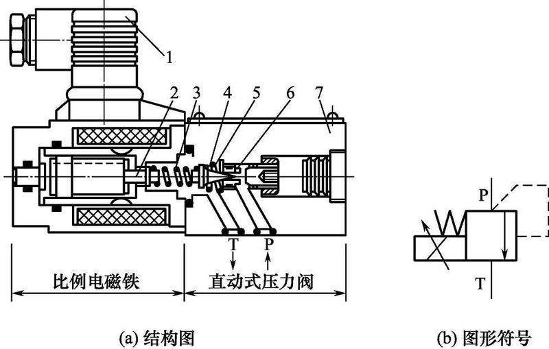
Figure 2-9 proportional pressure of direct electron without feedback valve
1-plugs; 2-coding iron pushers; 3-drive springs; 4-dig valve cores; 5-deep-proof springs; 6-drives; 7-drives
Figure 2-10(a) shows the structure of the directly mobile electron pressure valves in the form of bit transfer feedback, which, unlike the pressure valves shown in figures 2-9, shows a ratio of electromagnetics with a bit transfer sensor, with a detailed graphic symbol of 2-10(b). At working hours, a given fixed-value voltage voltage, proportional amplifier output controls the current, proportional electromagnetic power of the output of an electromagnetic thruster, which is proportional to the set value, functions on the conical core 9 by passing spring 7; at the same time, the actual position of the electromagnetic cortex pole (i. E. The position of the spring cortex 6) is detected by the sensorial shift sensor 1 and is fed back to the scale amplifier, using feedback voltage signals compared to the set voltage to control the shift of the cortex, i. E. The formation of a cort iron position closed circle within the valve. The impact of interference, such as friction, can be eliminated by the use of position transfer ring control, which ensures that spring six has a definite position proportional to the input signal and receives an accurate spring compression, thus obtaining an accurate pressure valve to control the pressure. The size of the electromagnetic force is determined by the load requirement within the maximum suction. This proportional pressure valve with feedback can be used when the system has higher requirements for repeat precision, molar rings, etc。
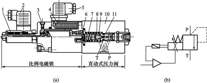
Figure 2-10 proportional pressure of direct-moved electron by bit valve
1-place transfer sensors; 2-sensor plugs; 3-gas bolts; 4-circles; 5-circle plugs; 6-circles; 7-transmission springs; 8-preserve oscillation springs; 9-cone valve cores; 10-valves; 11-valves
Figure 2-11 shows the ratio-flow valves for lead liquids with hand-on safety valves [figure 2-11(a) is a structure chart and figure 2-11(b) is a graphic symbol]. It has a lead stage at its upper end, a direct motion proportional pressure valve at its lower end, a power-grade main valve component (the cone valve structure)5 and a hand-to-hand limit pressure valve4 at its centre to prevent system overload. In figure a is a pressure oil vent, b is a spill vent and x is a remote control vent, which, when used, must be used with a lead control back to the tank from the outlet 2 without pressure. The valve works on the basis that it is essentially the same as the normal pilot spill valve except for the use of a proportional pressure valve at the lead stage. The hand-to-hand limit pressure valve, together with the main valve, constitutes an ordinary pilot spill valve, which, in the event of an accidental failure of an electrical or hydraulic system, is capable of immediately opening the system to unpressure to ensure the safety of the hydraulic system。
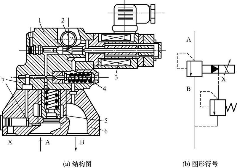
Figure 2-11. Lead-to-spill emission valves with hand-to-hand limit pressure valves
1 - precursor valves; 2 - spills; 3 - proportional electromagnetic; 4 - limit pressure valves; 5 - main valve components; 6 - main valves; 7 - stationary liquid resistance
Figure 2-12 shows the one-way zero-depressure valve. Compared to the normal one-way pressure reduction valve, the proportional pressure reduction valve replaces the repressure bolt with a proportional electromagnet。
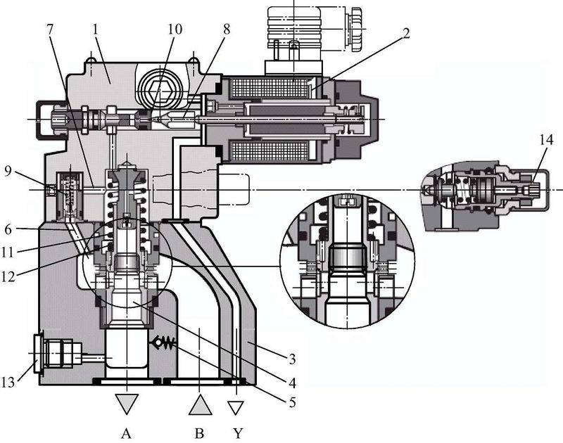
Figure 2-12 pressure relief valve
1-guard valves; 2-scale electromagnets; 3-principal valves; 4-channels; 5-way valves; 6,7-secondary pressure channels; 8-guard valves; 9,13-comberheads; 10-led valves; 11- springs; 12-main valves; 14-save valves
2. 2. 2 application of electrically proportional spill valves on engines
Emp spill valves for hydraulicly driven fans of engineering machines in the cooling system, the ungraded velocity of the fans is adjusted to the temperature of the cooling fluid, which is convenient, and can solve and install the unreasonable cooling problems of the mechanical cooling fans, which are changed only by changing the speed of the engine。
(1) the rationale for the scale valve system
The ratio fluid spill valve replaces the normal switch hydraulic valve by a manual adjustment device or the normal electromagnetic magnet, allowing for long-range, high-precision continuous control of hydraulic parameters, as shown in figures 2-13. In the hydraulic drive system for the cooling of fans of engineering mechanical engines, the input signal is the volume of electrical changes exported by the cooling liquid temperature sensor on the basis of the temperature of the cooling fluid of the collected engine, which, after treatment by a proportional amplifier, acts as a proportional electromagnetic magnet; the proportional magnet is used as an electro-mechanical converter to output the pull in proportion to the current of its sensor wire. This force acts on the core of the spill valve, so that, with the changes in the input flow, the spills can be altered to change the adjustment pressure of the throttle, control, output the hydraulic pressure, and automatically adjust the import/export pressure of the engine to cool the fan hydraulic drive system and the hydraulic motor to the temperature of the cooling fluid. The change in the pressure will speed up the cooling fan。
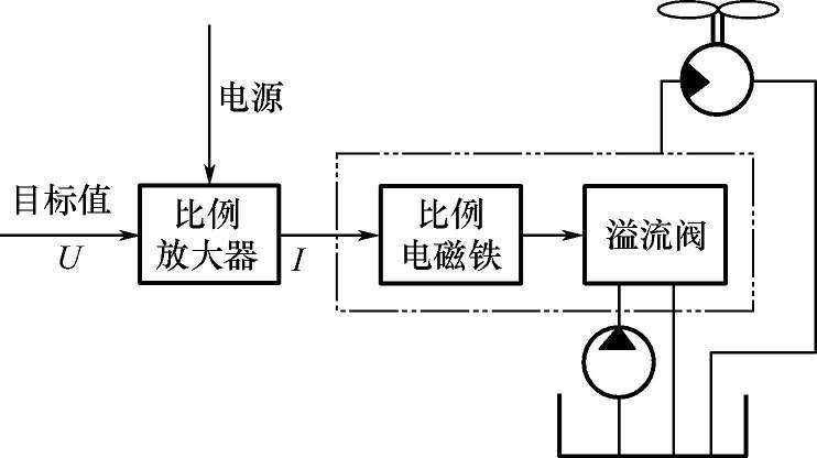
Figure 2-13: the rationale for the scale valve system
(2) test of ratio valve control properties
The control properties of the scale valves must be tested in order to determine the relationship between current f in the proportional electromagnetic wire ring at the entrance p. It requires that the flow through the test scale valve be constant and that the testing of the oil routes and test programmes be carried out as shown in figures 2-14。
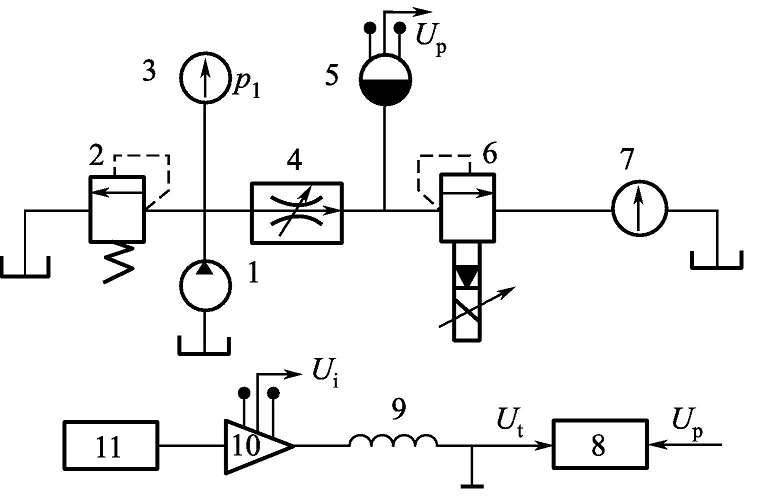
Figure 2-14 tested oil routes and testing programmes
1-oil source pump; 2-safety valve; 3-pressure table; 4-paced valve; 5-pressure sensor; 6-tested valve; 7-flowometer; 8-x-y recorder; 9-valve loop; 10-scale control amplifier; 11-sign generator
The system selects the ratio valve ebg-o3-c-t50 and the direct current power source with the skioi5-11 ratio control amplifier. Since the flow through the test valve is required to be constant (set value), the test path uses a constant flow source for oil, and valve 2 acts as a safe protection. Speed valve 4 is used to set constant flow through the test valve, the size of which is monitored and read out by flow count 7 in the pipeline。
In order to provide a continuous picture of the control characteristics curve of the scale valve, a triangulation signal from the ultra-low frequency signal generator 11 to generate 0. 01 to 0. 02 hz was passed to the proportional control amplifier 10; the ui signal was exported from the current detection hole on the ratio controller, which represents the size of the control current i in the circle. The entry pressure of the test valve was detected by pressure sensor 5 and converted to signal up output. When the triangulation signal gradually increases from zero to maximum value and then decreases to a cycle of zero, the test valve main valve opens the cycle gradually smaller and then opens to maximum experience. As a result, the entry pressure has changed a cycle, so the output signal for pressure sensor 5 is gradually increased from upmin to upmax and then down to umin. In the course of the test, the ui signal is delivered to the x-y recorder x-axis; the up signal is delivered to the x-y recorder y-axis, where the recorder depicts the control behaviour curve in continuous real time, as shown in figures 2-15。
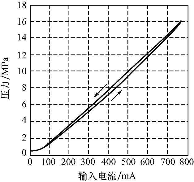
Figure 2-15 control curve
As can be seen from the control curve in figures 2-15, the entry pressure p of the selected scale valve varies with the input current i in the proportional electromagnetic ring. The entry pressure of the ratio valves increases when the input current i in the proportional magnetosphere increases; the entry pressure of the ratio valves decreases when the input current f in the proportional magnetosphere is reduced. In the system designed, the system pressure is the entry pressure of the proportional valve. Thus, the ratio valves can adjust the pressure of the system to the changes in the input currenti, and thus the pressure of the hydraulic motors on imports to change the speed of the fans。
2. 2. 3 proportional control system for water-powered load simulators for ship rudders
The ship rudder load simulator is a ground-based semi-physical imitation device used to simulate the external load of the wheel under laboratory conditions. The rudder is carrying more complex loads underwater, with water power, friction, inertia, etc. The load systems used to simulate such loads are generally characterized by heavy inertia, heavy load flow and required capacity. Rudder load simulators, including inert loads and hydraulic loads. Inertial loading is achieved through the equivalent rotation of the inertial disk, and hydrodynamic loading is achieved through the load-back path based on the proportional spill valve, avoiding the use of the large flow of electron server valves。
(1) hydraulic loading hydraulic systems
The rudder load simulator requires the following for hydrodynamic loading: hydraulic loading in the direction of the turn and turn of the rudder; constant load when the turn of the rudder stops; and stop loading when the turn of the rudder turns. In accordance with the above requirements, the hydrodynamic loader hydraulic systems are designed as shown in figures 2-16。
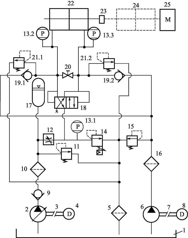
Figure 2-16 hydraulic principles for loaders
Triggers; 2-heavy-variant pumps; 3,7-axis; 4,8-electrically driven; 5,16-filter; 6-low-pressure high-voltage foliage pumps; 9,19-one-way valves; 10-precision filters; 11,15,12-spill valves; 12-spill valves; 13-pressure sensors; 14-scale spill valves; 17-capacitors; 18-liquid switch valves; 20-side ball valves; 22-loading tanks; 23-connecting institutions; 24-team hydraulic tanks; 25-inert load tanks
The hydraulic system consists mainly of the following two circuits。
1 load return path consisting of a heavily pressure variable pump 2, a one-way valve 9, a precision filter 10, a spill valve 11, a throttle 12, a builder 17, a proportional spill valve 14, a fluid switching valve 18, a pass-through valve 20, a spill valve 21 and a loading tank 22. When the rudder hydraulic tank turns on the 24-drive wheel, the loading tank provides resistance simulation of water power loads by connecting agency 23, which contains a rolling inertial load. Controls are used to control the back pressure when the tank is towed by controlling the spill pressure of the proportional spill valve14, thus controlling the load capacity of the active tank when moving. The function of the constant pressure variable pump is to provide the minimum flow of work required through the throttle 12 to the proportional spill valve when the wheel is stopped. Therefore, variable pump 2 selects a heaviness small charge variable pump with a set pressure of 21 mpa。
The refuelling circuit consists of low-pressure high-volume foliage pump 6, filter 16, spill valve 15 and one-way valve 19. The role of the recharge circuit is to supplement the volume increase with a cavity when the hydraulic tank is carried on passive motion. The leaf pumps in the recharge circuit are therefore a low-pressure high-flow pressure source, with an established pressure of 0. 5 mpa for spill valve 15. The system uses high-pressure small and low-pressure high-voltage pumps as a hydraulic power source, with low-efficiency and high-efficiency characteristics. At the same time, the system avoids the existence of complex hydraulic inertial systems and the use of more costly electron server valves, which are simpler and easier to achieve。
(2) control methods and effects
A control system as shown in figures 2-17 is designed in accordance with the hydraulic systems and working requirements of the above design。
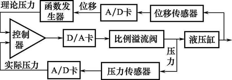
Figure 2-17: control system rationale figure
The size of the rudder angle can be calculated based on the shift of the rudder hydraulic tank piston to the geometry of the rudder. The function generator receives the signal generator of the hydrodynamic load to which the steering axis is exposed at that position, according to the size of the rudder angle. When the system works, the corresponding value of the measured rudder-water-powered load is added to the function generator at the appropriate intervals and a table of different rudder-driven loads is obtained. When the function generator acquires the current rudder angle of the rudder axis through the data acquisition system, the value of the hydrodynamic load is worthwhile through a checklist or linear plug. When ships actually sail at different speeds, there are different rudder-water-powered load curves. Therefore, the function generator can perform a number of hydrodynamic load signals at different rudder angles at different speeds. At the same time, in order to meet the working requirement of "the wheeling engine is not carried on board" the function generator will also need to make a determination as to the change of position of the hydraulic tank. When the function generator judges that the rudder axis moves in a direction close to the medium, the theoretical value of the hydrodynamic load of the function generator directly yields zero. Function generator output normal if judged to be far from medium direction. The hydrodynamic load values obtained above can calculate the theoretical pressure values that should be controlled by the loading cavity. The formula is shown in formula 2-1。
P = f/a+p1 (2-1)
In form f - theoretically required to load the water power load
A - the area of actual stress of the hydraulic pistons
P1 - the pressure of another cavity of the hydraulic tank is measured by the pressure sensor。
Accomplishment of pre-relationure control for the electron control system, maintaining a certain output power requires a certain control voltage of the electron valve, and the system is therefore a zero differential system. The spill pressure of the proportionate spill valve is roughly proportional to the input voltage signal, and for a certain load to be maintained, a certain input voltage is required。
In order to maintain the output of the system, the weight of the error must always be present and play a major role, if it is controlled by an ordinary pid. It is understood by the control theory that, while the fractional link can eliminate the system's static, it will slow down the system's dynamic processes and the stability of the system will be undermined by excessive fractional effects. In order to be able to eliminate large follow-up errors, and to avoid the adverse effects of excessive credits, the system uses the method of pre-speed feedback with closed-ring ratio control, the principles of which are shown in figures 2-18。
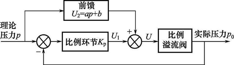
Figure 2-18: pre-reventory control principles
In this method, the total control of the proportional spill valve is:
U=u1+u2 (2-2)
Available by format (2-2): pre-reventive control of voltage u2 plays a major role in dynamic follow-up; closed loop control of voltage u1 plays a fine-tuned role, corresponding to the principle of error elimination by pid controllers. Therefore, the accuracy of the relationship between the input charge and the spill pressure determines the effectiveness of the actual control. The proportional spill valves used in the system are repeatedly marked at the laboratory site and the spill pressure is associated with the input voltage curve, as shown in figures 2-19。
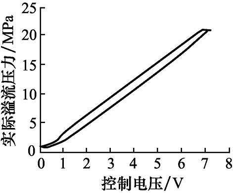
Figure 2-19 proportional spill valve input relative to spill pressure curve
As can be seen from figures 2-19, the proportional spill valve is linearly related to input voltage values at both stages of increase and decline, but there is a clear lag. The k and b values of the formula (2-3) and formula (2-4) are available by line, thus allowing the ratio overflow valve to control the mathematical relationship between voltage u and spill pressure p:
P = klu+bl (2-3)
Under p = k2u+b2 (2-4)
As u and p satisfy different relationships at the up and down stages respectively, the direction of the theoretical pressure value needs to be judged in the controller, using asymmetrical variant relationships. When theoretical pressure values are increased, the front feed controller applies the relationship style (2-3); when reduced, the front feed controller applies the relationship style (2-4)。
Control effects figure 2-20 shows the actual control effects of combining pre-use feed control with ratio control. Since a triangle is a more dynamic wave shape, it is sufficient to test the dynamic follow-up properties of the loading system。
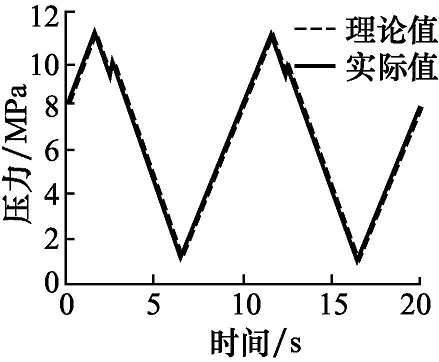
Figure 2-20 triangular wave pressure following
As can be seen from figures 2-20, the actual curve follows well except for a slight oscillation at the turning point of the pressure. Since the control value of the pressure during the front feed control process is based on changing trends, the control pressure shows a relatively small shock at the turning point. The ship rudders do not undergo such drastic changes in the course of their actual operations, so that the control strategy does not have adverse effects such as additional vibrations on their practical application。
2. 2. 4 the electron ratio pressure reduction valves are used to regulate the flow of hydraulic pumps from excavators
Hydraulic systems change the flow of hydraulic work pump output mainly through pressure compensation variable institutions, so that engine speeds are constant in the selected position. The pressure-compensation variable for the 350 hydraulic-exploitation systems consists mainly of constant power and load sensor adjustments。
(1) hydraulic reduction valves
The main component of constant power regulation is the electron-scale pressure-relief valve, known as the prv valve, which is an electromagnetic valve, unlike the normal electromagnetic valve, which controls the action of the coil with a pulse signal from the electronic controller。
The working model of the valve is simplified as shown in figures 2-21。
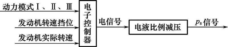
Figure 2-21 working pattern of the electron ratio pressure reduction valve
The electronic controller integrates, analyzes the selected power mode, engine re-pacing and the actual engine re-pacing, forms a telecommunications signal to the electron ratio pressure reduction valve, moves the slide valve, opens a control channel, directs the oil through the valve and turns it into a ps signal. One of the three variables above is changed, leading to a change in the ps signal。
According to caterpillar, when the motor actually turns 250 r/min lower than the theoretical rate, the electron-rate reduction valve sends a ps signal, alters the tilt of the tilt, reduces the output flow of the main pump and prevents the engine from having to shut down. In front of the right-hander of the driver's room, there is a spin button, which is selected for the engine to turn. It has ten barriers, each at 900r/min, 1020r/min, 1160r/min, 1,300r/min, 1470r/min, 1590r/min, 1700r/min, 1800r/min, 1900r/min, 1970r/min. In power mode i, ii, the pulse width is constant, and the pprv valve does not send a ps signal when the engine turns up to the set value. The greater the pulse width of the electron-rate-reducing valve, the greater the magneticity, the smaller the valve opening。
(2) reconciliation of the flow of former and post-work pumps
The handle is activated with constant power. At this point, the output of the pump is determined by the pressure of the pump. There are three power levels, i. E. Power mode i, ii, iii. In power mode iii, power output is 100%; in power mode ii, power output is 90%; in power mode i, power output is 70%. The power pattern changes, the ps signal from the pprv valve changes, and the volume of pump output changes。
The flow is controlled by load pressure signals. When the handle is used for a local trigger, the pump output flow is determined by the handle trigger; when the handle is in the middle, the pump output is the smallest. The work pump output curve is shown in figures 2-22。
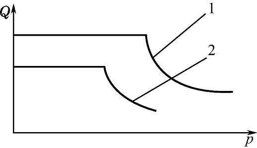
Figure 2-22 work pump output curve
1-hand power output control; 2-hand handle local trigger load transmission sensor
The regulation of the work pump flow is performed by the ps signal from the electron-scale pressure-relief valve, which functions as a constant power regulator for the main pump upon arrival of the pre-pump, post-pump, and the principles of the regulation are shown in figures 2-23。
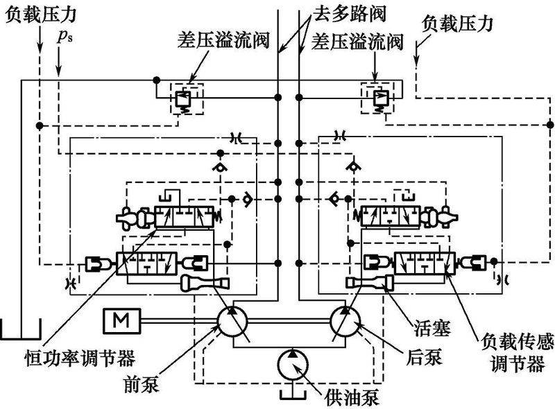
Figure 2-23 work-pump flow regulation principles
When the output pressure of the work pump is equivalent to the load pressure, the valve core of the load sensor is moved to the other end by the spring force. When the pressure of the front pump is greater than the sum of the spring pressure pt of the ps signal oil and the constant power regulator, the core moves to the right, the pressure oil flows from the work pump, and there is a one-way valve, which moves through the helipower regulator, the load sensor adjuster, and acts on the large cavity that connects the tilt disc piston, moving the piston to the right, increasing the tilt of the tilt and increasing the flow of the work pump. The right shift, which connects the oscillation pistons, leads to a right shift in the slider of the electron-rate pressure-reducing valve, thereby changing the position of the electron-rate pressure-reducing valve core vis-à-vis the slider, leading to a change in the opening of the oil lanes, with the core moving again under the pressure differential until it is balanced in the new position. On the other hand, if pd1960kpa (pl is a load pressure), the carrier sensor valve core begins to move, pushes the core of the valve connected to the tilt disk, and increases the tiltboard angle until the next balance position, i. E. Pd-pl = 1960kpa。
In terms of load sensor regulation, 350 hydraulic systems have the advantage of typically typical hydraulic systems。
The greatest feature of the 350 hydraulic system is engine selection. Any speed block can meet the changing demands of the load with the assurance that the engine will not go off. The system allows engines to fluctuate at speeds below the selected stop speed of 0 to 250 r/min, avoids frequent swinging of the work pump ramp and better adapts to complex conditions. At pd≈pl, the electronic controller sends a pulse signal to the electron proportional pressure reduction valve after analysis based on the selected change in the power mode, the engine turn-off and the engine's actual turn-off. The ps signal from the hydraulic ratio reduction valve still regulates the flow of the work pump to allow full performance of the whole machine. For example, the working pressure of hydraulic excavators applies to the hardness of a mine layer, such as in the case of less rigid deposits, where the system maximizes the flow and speed of work; in the case of more hard deposits, the system reduces the flow and reduces the speed of work。
All of this takes place in a state of constant power。
(4) summary
The pressure-compensation variable, consisting of a hydraulic ratio-relief valve, is further adjusted to the flow of hydraulic work pumps based on the small changes in the selected power mode, engine re-pacing and the actual engine re-pacing, so as to stabilize engine output power, reduce fuel consumption and operate easily。
In the hydraulic system of the 350 hydraulic excavators, in order to reduce fuel consumption, there are three pressure switches, namely, walk-through pressure switches, reverse pressure switches and machine pressure switches. When these pressure switches do not move, i. E. When all control valves are in the middle, the engine system automatically slows the engine down to a low speed after 3s in order to reduce fuel consumption; when any primary control valve moves, the engine system automatically rises the rate to a given position to accommodate the production effort。