1. 3. 8 scale valves
The volume of hydraulic pressure from the emission control valve is proportional to the telecommunications number entered. It significantly simplifys hydraulic systems, achieves control of complex procedures and motion patterns, achieves remote control through telecommunications, and significantly increases the control level of hydraulic systems compared to the normal hydraulic valves for manual regulation and decomposition control; and has a clear structural and cost advantage compared to the electron server valves, although their dynamic and static performance are somewhat less robust, to meet most situations where the requirements for dynamic static performance indicators are low. The performance of the electron scale valve has been close to, or even exceeded, the service valve with the advent of the electron-serving ratio valve。
(1) ratio control doctrine
The electron ratio valves are usually composed of electrical-mechanical converters, hydraulic amplifiers (lead valves and power-level main valves) and detection feedback agencies (figures 1-37). In the case of single valves, no lead valves。
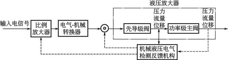
Figure 1-37 composition of electron ratio valves
The electron ratio valve is the main power magnification element of the ratio control system, which controls the pressure, flow, etc. Of the hydraulic system in proportion to the input telecommunications command。
(2) classification of electron ratio valves
Proportional valves can be divided into three main categories by their primary function: pressure control valves, flow control valves and direction control valves, each of which can be divided into two structural forms of direct control and lead control, which are used in small flow small power systems and lead control in large flow high power systems. The classification of electron-scale valves is shown in figures 1-38。
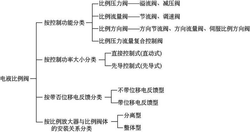
Figure 1-38 classification of electron ratio valves
(3) emp pressure valve
1 figures 1-39 are the structure and graphic symbols of a direct electron-scale pressure valve without feedback, figures 1-39 (a) are the structure, and figures 1-39 (b) are the graphic symbols. It consists of proportional electromagnetic and direct pressure valves. The structure of the direct pressure valve is similar to that of the lead valve of the normal pressure valve, unlike the pressure spring of the valves, which is replaced by a transfer spring of 3 and the manual calibration of the bolts, which is replaced by a proportional electromagnet. The spring 5 between the cone core 4 and the valve 6 is used primarily to prevent the vibration of the core. Valve 7 is the direction valve. When the proportional magnet enters to control the current, the thrust of the second output of the cortex is applied through the flow spring 3 on the conical core 4 balanced with the liquid pressure on the cone core, which determines the opening between the cone core 4 and valve 6. Because of the small change in opening volume, the variation in transmission spring 3 variants is also small, and if the effects of liquid power are ignored, the controlled pressure is considered to be proportional to the output electromagnetic force of the proportional electromagnet, thus being comparable to the controlled current of the imported proportional electromagnet。
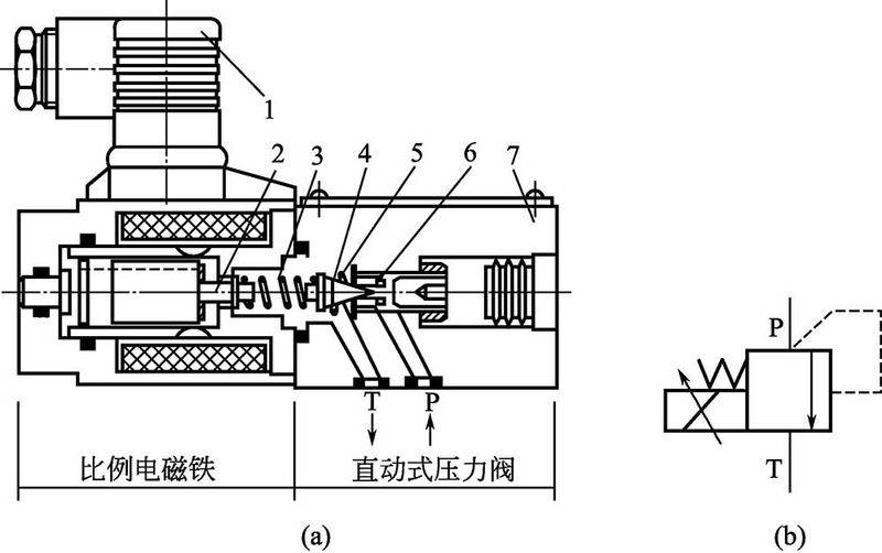
Figure 1-39 structure and graphic symbols of direct electron-scale pressure valves without electrical feedback
1-plugs; 2-coding iron pushers; 3-drive springs; 4-dig valve cores; 5-deep-proof springs; 6-drives; 7-drives
Characteristics of direct-to-scale electron pressure valves without feedback: such pressure valves, in addition to being used separately as pressure-reducing components in small flow settings, are more integrated as lead valves with common spill valves and pressure-reducing valves, which constitute a pre-guided charge-rate charge-proportion valves without electrical feedback, a pre-guided charge-reducing valve, and a change in the size of the incoming current, which can change the electromagnetic force, thereby changing the pressure on the foregone of the conductor valve (i. E. The upper cavity of the main valve) and achieving control over the import or export pressure of the main valve。
Figure 1-40 shows the structure and graphic symbols of the 2-bit transfer feedback-based direct flow pressure valves, and figure 1-40 (a) shows the structure and graphic symbol of the shift-based direct flow-rate pressure valves. It differs from the pressure valves shown in figures 1-39 where the ratio electromagnetics have a bit-shifting sensor 1 with the detailed graphic symbol 1-40 (b)。
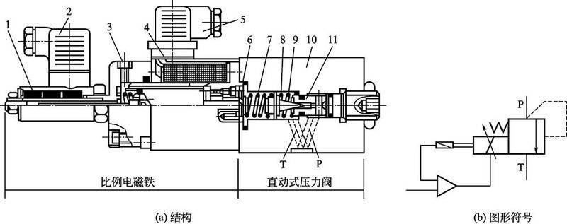
Figure 1-40 structure and graphic symbols of direct-to-motion electron pressure valves
1-place transfer sensors; 2-sensor plugs; 3-gas bolts; 4-circles; 5-circle plugs; 6-circles; 7-transmission springs; 8-preserve oscillation springs; 9-cone valve cores; 10-valves; 11-valves
Characteristics of the ratio-to-scale electron pressure valves of the bit-transfer feedback type: at work, the given fixed-value voltage voltage, the proportional amplifier output correspondingly controls the current, the electromagnetic force of the ratio-to-set output of the electromagnetic thruster, which acts on the conical core 9 by passing spring 7; at the same time, the actual position of the electro-sensor of the electro-sensor is detected (i. E., the position of the spring seat 6) and is fed back to the scale amplifier, using feedback voltage signals compared to the set voltage to control of the rank iron position, i. E., the formation of a title bar position closed ring control inside the valve. The impact of interference, such as friction, can be eliminated by the use of position transfer ring control, which ensures that spring six has a definite position proportional to the input signal and receives an accurate spring compression, thus obtaining an accurate pressure valve to control the pressure. The size of the electromagnetic force is determined by the load requirement within the maximum suction。
This proportional pressure valve with feedback can be used when the system has higher requirements for repeat precision, molar rings, etc。
Figure 1-41 shows the structure and graphic symbol of the pre-restriction pressure valve, figure 1-41(a) shows the structure of the pre-restriction pressure valve and figure 1-41(b) shows the graphic symbol. The upper part of the valve is the lead stage, which is a direct, proportional pressure valve, the lower part is the power-grade main valve component (the cone valve structure with cones)5 and the central part is equipped with hand-to-hand pressure valve 4 to prevent system overload. In figure 1-41(a), a is a pressure oil vent, b is a spill vent and x is a remote control vent, which, when used, must be used in a first-directed control of the oil from an outlet 2 to the tank。
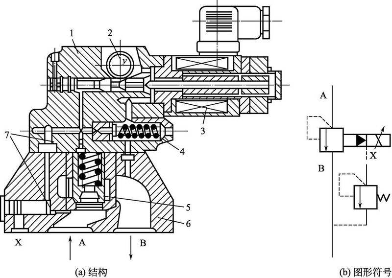
Figure 1-41 structure and graphic symbol of a lead-to-strength charger-to-pressure valve
1 - precursor valves; 2 - spills; 3 - proportional electromagnetic; 4 - limit pressure valves; 5 - main valve components; 6 - main valves; 7 - stationary liquid resistance
The valves are essentially the same as the normal lead spill valves except for the use of proportional pressure valves at the lead stage. The hand-to-hand limit pressure valve, together with the main valve, constitutes an ordinary pilot spill valve, which, in the event of an accidental failure of an electrical or hydraulic system, is capable of immediately opening the system to unpressure to ensure the safety of the hydraulic system。
The structure of the 4-scale pressure relief valves is shown in figure 1-42, which shows the structure of the one-way ratio reduction valves。
The proportional pressure reduction valve replaces the adjusted bolt with a proportional electromagnet, compared to the normal one-way pressure reduction valve。
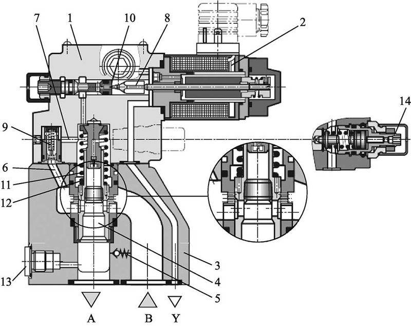
Figure 1-42 structure of one-way proportional pressure reduction valves
1-guard valves; 2-scale electromagnetic; 3-principal valves; 4-principal valves; 5-one-way valves; 6,7-secondary pressure channels; 8-prime valves; 9,13-colour heads; 10-prime valves; 11-springs; 12-principal cores; 14-security valve
(4) proportional fluid flow valves
Figure 1-43 shows the structure and graphic symbol of a normal direct-dynamic-scale electron-saving valve, figure 1-43 (a) shows the structure, and figure 1-43 (b) shows the graphic symbol. The power control ratio electromagne 1 direct-drive throttle core (sliding valve)3 is proportional to the input telecommunications number of the electromagnet in relation to the axle shift (i. E. The opening of the valve axis) of the valve 4。
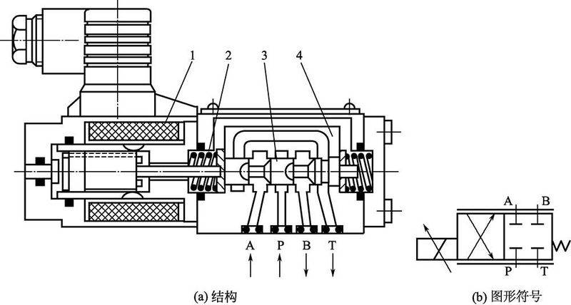
Figure 1-43 structure and graphic symbols of normal direct-to-motion electron ratio throttle
1-scale electromagnetic; 2- spring; 3-scaling valve core; 4-valve body
The valve structure is simple and inexpensive, and the slide valve functions are open in addition to the usual closed mode as shown in figure 1-43(a); however, because of the absence of pressure or other measures to detect compensation, the work is subject to friction and hydraulic power, so the control is not sufficiently precise and suitable for low-pressure small flow hydraulic systems。
Figure 1-44 shows the structure and graphic symbols of the 2-bit transfer feedback-based straight-scale electron ratio-referral, and the structure of 1-44 (a) and the graphic symbol of 1-44 (b). It consists of a throttle valve, a fixed-depressure valve as a pressure repairer, a one-way valve and an electro-sensor. The position of the throttle core 3 is detected by the transposition sensor6 and fed back to the scale amplifier. A one-way valve is open and does not have a proportional flow control function when the flow of liquid flows from b to a。
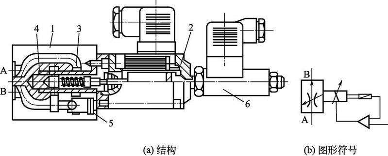
Figure 1-44 structure and graphic symbol of the direct-moveable electron ratio-referral in bits of feedback
1-valves; 2-scale electromagnets; 3-scaling valve cores; 4-fixed pressure reduction valves as pressure compensaters; 5-one-way valves; 6-electrically transposition sensors
This ratio-to-speed valve can overcome the effects of interference and has better static, dynamic properties, mainly for systems with smaller flows。
(5) electro-liquid ratio direction valve
The electron ratio control valve can control the direction and speed of the conductor by the polarity and size of the range of the input telecommunications, while controlling the flow direction and flow of hydraulic systems. Under constant pressure differentials, the flow through the electron ratio direction valve is proportional to the amount of the mark entered for the telecommunications signal, and the direction of movement depends on whether the proportional magnet is motivated。
The structure and graphic symbols of the normal direct-moved electromechanical ratio-direction valves are shown in figure 1-45. They consist mainly of two proportional magnets 1, 6, valve 3, valve cores (quartet slide valves)4 and are composed of springs 2 and 5. When the electromagnetic 1 is wired, the valve core moves right, the oil vent p and b, a and t, while the opening of the valve is proportional to the input flow of electromagnet 1; when the electromagnetic 6 is powered, the core moves left, the oil vent p and a, b and t, the opening of the valve is proportional to the input flow of electromagnet 6. Unlike the server valve, the four control edges of such valves have a large cover and the end spring has a certain installed pre-compression. The valve has a large median dead zone for its stable state control properties. In addition, due to interference with friction and valve fluid power, the core positioning of this direct-to-peer electromechanical fluid is less accurate, especially in the case of high-pressure mass flow. In order to increase the control accuracy of the electron ratio direction valves, the vertically mobile electron ratio-to-flow valves can be used in place-transfer feedback。
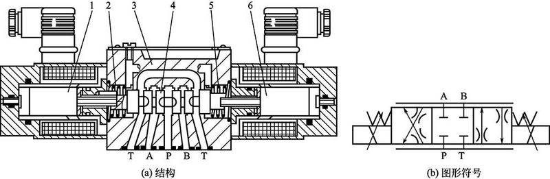
Figure 1-45 structure and graphic symbols of the normal direct-to-peer electron-to-penetrated throttle
1,6-scale electromagnet; 2,5-to-cut spring; 3-valve; 4-valve core
The structure of the pressure-depression pilot + main valve spring-positioned electron-proportion valve is shown in figure 1-46. Its lead valves are able to export control pressures proportional to the input telecommunications, and two export pressures corresponding to the input signal polarity, are directed to the main valve core, respectively. At both ends of the 2nd, the main valve core 2 is positioned proportional to the input signal, using the balance of its liquid pressure on both ends with the spring power of the centered spring 3. The introduction of a pressure-reducing lead-up does not require continuous consumption of lead-control oils, as is the case with a pilot spill with similar principles. The lead control oils may be internal or external, and if the lead control pressure exceeds the specified value, the lead pressure may be reduced by a first guidance decompression valve. The main valve is in the form of a single spring-to-medium spring, with a pre-compression level, and the main valve core is in the middle when the lead valve does not enter the signal. Single springs simplify the structure of valves and make them symmetrical。
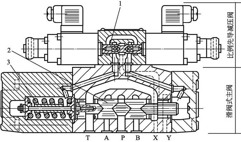
Figure 1-46 structure of the pressure-reducing lead stage + the main valve spring-positioned electron-proper valve
1-leave pressure reduction valve core; 2-main valve core; 3-red spring