Plc's connection to the temperature sensor depends on the type of output signal of the temperature sensor and the input module configuration of the plc, with different connecting options corresponding to different transmission principles, connection complexity and measurement accuracy. The following is a textual and detailed description of the type of connection most commonly used at the industrial site, with a clear picture of the application of the programmes and key concerns。
I. Core classification logic
The output signals of the temperature sensor can be grouped into three broad categories: analogue, digital, switch, and plc is required to select the corresponding input module (simulation input module ai, digital input module di, communications module) according to the type of signal. Of these, analogue connection is the basis for industrial temperature measurement, digital connection is the preferred option for high precision, long-range transmission, and switch connection only applies to simple scenes where the temperature is lower or higher。
Option 1: simulation output temperature sensor + plc simulation input module (most commonly used)
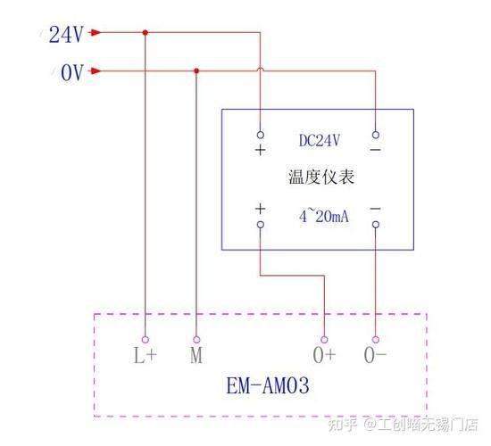
The core of such connections is the conversion of detected temperature signals by temperature sensors to standard analogue signals (4-20ma current signal, 0-10v voltage signal, industrial standard), and the transfer of analogue input modules to plc via a conductor line, which then convert analogue signals to numerical quantities for plc's cpu operation。
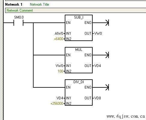
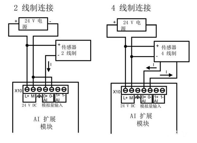
Integrated temperature adapters applying sensor type with analogue output, e. G. Pt100 thermal resistor integrated transmitter, k-type heat puppet integrated transmitter, ntc thermal sensitive resistor, etc. Such sensors are internalized into signal-modified circuits that directly convert the physical volume of temperature to a standard analogue signal without the need for additional conversion equipment. The plc module requires plc to configure the simulation input module and the input specifications of the module need to match the output signal type of the sensor (e. G. 4-20ma input type, 0-10v input type, or generic simulation input module). For example, the siemens s7-200 smart eem ae04 module, the mitsubishi fx series fx 2n-4ad module and the rockwell micro800 2085-ia4 module. Specific connections take the example of 4-20ma current signals, which are the most stable at the industrial site, and are linked to: (1) power supply links: integrated temperature transmitters usually require external power supply, which is divided into two-line, three-line, four-line systems, two of which are the most commonly used energy-saving programmes. The two conductors of the two-lined transformer perform both electrical and signal transmission functions, the main end of the power-synthesis transducer, the positive end of the negative end-end analogue input module of the transmitter, and the negative end-synthesis of the signal-sync input module to form a closed loop. (2) connectivity: the simulator output end of the temperature sensor is connected by shielding the double winch to the corresponding channel end of the plc simulation input module. For 0-10v voltage signals, the connection is similar, provided that the transmission distance of the voltage signal is short (usually not exceeding 50 m) and is less resistant to interference than the current signal. (3) plc internal processing: after the connection has been completed, the simulation route configuration will need to be performed in the plc programming software, setting the type of signal (e. G. 4-20ma), the range of the range (e. G. The measuring range of the sensor 0-200°c) and converting the original values collected by the simulation module (e. G. The numerical range of the 4-20ma corresponding module 0-27648) to the actual temperature value, the formula being: the actual temperature = (module capture value - minimum) x (maximum temperature range - minimum temperature range) ÷ (mix maximum - minimum module range) + minimum temperature range. Key care (1) transmission cables need to use shielded winch lines, one end of the shield, to reduce electromagnetic interference at industrial sites and to ensure the stability of signals. (2) a current signal of 4-20ma can be transmitted at a distance of up to hundreds of metres and is suitable for long-range temperature measurements; 0-10v voltage signals are transmitted at a relatively short distance and are suitable for a close, disruptive, small range. (3) the route of the analogue input module needs to match the type of sensor, and if thermal resistance or thermal dolls are used to connect directly to the analogue module (non-integrated transformers), the module needs to have a special heat resistance/thermal doll input channel and to be equipped with a corresponding compensatory guide and cold end compensation. Iii. Option 2: digital quantities output temperature sensor + plc communications module / plc with communication interface (high accuracy, long range preferences)
At the heart of such connections is the use of a temperature sensor to export temperature data using a digital communication protocol, which allows two-way transmission of data by means of communication cables connected to the plc communication module or plc with its own communication interface. The programme's measurements are highly accurate and resistant to interference, allows for long-range transmission and supports interlinear connections of multiple sensors and saves on wiring costs。
Temperature sensors with digital communication interfaces of the type applicable to sensors, such as smart temperature transporters (support to modbus-rtu, profibus-dp, profinet, devicenet, etc.), digital thermal resistance/thermal voltage sensors, etc. For example, the pt100 smart temperature sensor for the modbus-rtu protocol is the most commonly used digital temperature sensor for industrial sites. The plc module requires direct connection if plc has its own cpu interface (e. G. Rs485, ethernet interface) or, if not, a dedicated communication module such as rs485 communications module, profibus-dp master station module, profinet ethernet module, etc. For example, siemens s7-300 cp341 communication module (rs485), mitsubishi fx series fx4n-485bd communication panel, rockwell 1769-aentr ethernet module, etc. The specific mode of connection is the example of the modbus-rtu protocol (rs485) most commonly used at the industrial site. The connection process is: (1) extended structure: using a bus-based extension structure that connects the rs485 interface (a, b end) of all digital temperature sensors by shielding the double winch line to form a rs485 bus with terminal resistance (usually 120 times) at both ends of the bus to remove signal reflexes and ensure the stability of communications. (2) main setup: in the communications network, plc is the main station, all temperature sensors are the only station address (e. G. 1,247) from which each station is to be located, and the communication parameters (port rate, data bit, stop slot, validation slot) are to be aligned to ensure consistency in the communications parameters from the main station. (3) connectivity: the communication module that connects the a and b ends of the rs485 bus to plc or the corresponding end of the rs485 interface with the cpu itself, one end of the shield layer. (4) plc internal processing: once the connection has been completed, the communication parameter configuration in the plc programming software, as well as the reading of the temperature sensor memory data through a dedicated communication command (e. G., the modbus-rtu reading and writing instruction), obtains the actual temperature values directly, without the need for analogue-to-number conversion, and simplifys the programming process. Key care (1) communication protocols must be consistent, with the same communications protocols as those used by the main station and from the station, otherwise data transmission cannot be achieved. (2) the number of sensors connected to a bus is limited, depending on the communication capability of the terms of the communication agreement with plc, such as the modbus-rtu agreement, which supports up to 247 stations. (3) transmitting cables are subject to a double-barrel shielding line with a distance of up to thousands of metres, suitable for long-range, multi-point temperature measurements at large industrial sites. Option 3: switch output temperature sensor + plc digital input module (only for temperature alarm)
At the core of such connections is the temperature sensor's built-in temperature switch, which, when the detected temperature reaches the predefined upper or lower limit, the sensor's switch output contact is subject to a break-out (high-intensity contact closed or closed-off), and the digital input module that is transmitted to plc via a steering line, which only determines whether the temperature is beyond the preset range and cannot obtain a specific temperature value。
The application of the sensor type temperature switches, temperature sensors with the output of switches, such as mechanical temperature switches, electronic temperature switches, etc. The functions of such sensors are single and can only achieve temperature alerts at upper and lower limits and cannot be measured accurately. The plc module requires plc to configure a digital volume input module (di module) whose input voltage specifications are to match the control voltage of the sensor's output contact (e. G. 24v dc, 220v ac). Specific connective means (1) power supply links: switch output-type temperature sensors usually have contact points that are passive and require external provision of working voltage, which is at a level consistent with input voltage in the plc digital input module. (2) connectivity: the positive end of the external power source at one end of the heat sensor's switch output contact point, the corresponding end of the channel at the plc digital input module at the other end, the negative end of the external power source at the public end of the plc digit input module to form a closed loop. When the temperature reaches the predefined value, the contact closed, the corresponding channel of the plc digital input module detected the signal, and the cpu of the plc judged it to be "1"; when the temperature did not reach the predefined value, the contact was disconnected and the plc judged it to be "0". Key care (1) the programme can only achieve temperature alarms at upper and lower limits, does not have specific temperature values, applies to scenes where temperature measurements are less accurate and require ultra-restrictive protection, such as the temperature protection of electric appliances, the temperature of water tanks, etc. (2) connections need to be made with regard to the type of contact point (open or closed) and the corresponding logical treatment in plc procedures according to actual needs. V. Special programmes: thermal resistance / thermal dolls directly connected plc specialized input module (non-variant)
For pure thermal resistance (e. G. Pt100, cu50) or pure thermal voltage (e. G. K, j, s), some plc supports direct connection through dedicated thermal resistance/thermal voltage input modules, without the need for additional integrated delivery units. The internalization of the module into signal-modified circuits, cold-end compensatory circuits and a/d conversion circuits allows direct conversion of thermal resistance/thermal voltage changes or thermal power changes into numerical volumes for plc cpu processing。
Connection: the output end of the thermal resistance / thermal electromechanical doll, the thermal resistance / thermal volleyball input module, which is connected to the plc via a dedicated compensatory guide, automatically compensates the cold end and converts the signal. Key care: thermal electrical resistance links need to be wired (two-line, three-line, four-line) and trilinear and four-lined measurements are more accurate than two-lined; the thermoelectric dolls need to be connected with a dedicated compensatory guide and ensure that the models of the compensating circuits are consistent with those of the thermoelectric dolls to reduce temperature measurement errors. General connector care matching power: the electric voltage of the temperature sensor needs to be consistent with the power voltage actually provided to avoid damage to the sensor or inability to function due to the mismatch of the voltage. Anti-disruption measures: there is a large amount of electromagnetic interference at the industrial site, which requires the use of shield cables when connected and one end of the shield layer to the ground; cables simulating a volume signal and a number of signals need to be lined separately to avoid cross-cutting interference; and both ends of a communications cable need access to terminal resistance to ensure the stability of communications. Module configuration: after the connection is completed, the corresponding module configuration (e. G. Simulation volume signal type, communication parameters, thermal resistance/thermal doll type, etc.) must be performed in the plc programming software, otherwise plc cannot correctly identify and process data. Wire specifications: wires must be placed away from powerful sources of electromagnetic interference, such as power lines, frequency transformers and electric generators; when transmitted at long distances, preference is given to 4-20ma current signals or digital communication protocols, avoiding the use of 0-10v voltage signals。