0 foreword
The raw material grinding of the sichuan cement company ltd. 5000t/d cement production line used two mls3626 mills. The mill was stabilized by a pressure frame and transmitted loads, but the mills could not be elevated. The grinding machines are therefore subject to manual fabric before they are turned on, work conditions are poor and workers are labour-intensive; they are not able to perform functions such as light-loading start-ups and rapid lifts in emergency situations, with greater impact on the main brakes, grinding panels and grinding panels at short notice, significantly reducing their useful life and reducing the mill's operating rate. In order to address the above issues, the owners would like to use the six months of kiln overhaul to retrofit the two mills。
1 pre-reform analysis
During the review of the ground plank information and the measurement of the actual installation at the mill site, the analysis resulted in a grinding and pressure framework that, in the overall lifting of 250 mm, did not interfere with other grinding components, such as the sealed windway, the pollinator and the shell; the grinding of the mills, such as grinding slabs, connectors and slabs, which, by calculating their strength, could meet the intensity requirements of the grinding group lifting; the grinding of 15 degrees in the static state and the direction of lead pits; the grinding of the grinding poles in the lifting of the grinding force in the lifting force; the grinding of the grinding force centre in the grinding force; and a gradual reduction of the lead protagonal angles, which would be unsafe; the grinding of the milling would not be able to reach the plate outside of the plate; the restoration of normal working conditions would require an increase in the grinding of the grinding gear (e. E. L. L. L. D. . As a result of the above analysis, it was determined that the retrofit was carried out in three parts: (a) an increase in grinding lifting units; (b) a strengthening of the pole-stretching device in conjunction with the pressure frame; and (c) the replacement of hydraulic systems。
2. Adaptation process
2. 1 increased milling lifts
The main function of the milling lift is to ensure that the milling is kept at an angle of about 15 degrees during the lifting and landing. The additional grinding lifts consist mainly of lower connectors, connect boards, slabs, spring boards, gasket groups, etc. (see figure 1)。
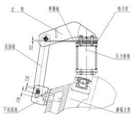
Figure 1
The grinding and pressure frames will be properly fixed as required by the relevant information at the site, then lined and drilled with screw-lined holes on each of the grinding racks and pressure frames, respectively, and will be fitted with connectors, connectors, slabs, springboards, and will eventually complete the upgrades by adjusting the size of the gasket groups to reach the values of x, y and z in the maps。
2. 2 tighter improvements
The mill was originally designed to have a stress-up frame function in a state of overhaul. The lifting pole is transmitted by six m42x200 bolts when lifting the pressure frame. The six bolts also bear the burden of lifting the grinding group, which is clearly unreliable and unsafe. Through on-site and drawing analysis, we are considering the addition of plugs (as figure 2) between the pull and the pressure frame, so that the boost required by grinding can be transmitted directly to the pressure frame by pulling the pole. The bolts are much less powerful and their safety is assured。
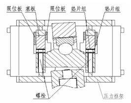
Figure 2
Tighter improvements have mainly added parts such as limit plates 1, plugs, limit plates 2, gasket groups, etc。
2. 3 hydraulic system modification
The original grinder hydraulic system is relatively simple and does not enhance or reduce the grinding function, hence the need to adapt the original hydraulic system. The elements include the repositioning of hydraulic piping, the replacement of hydraulic stations, the modification of control systems, etc. Modified hydraulic principles (see figure 3)。
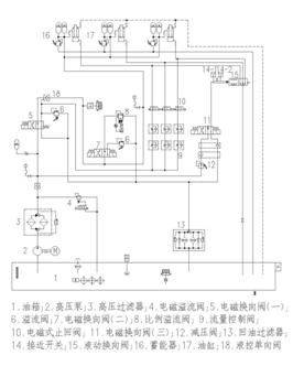
Figure 3 hydraulic principles
The control method is as follows: first, the oil pump is activated, the electromagnetic switching valve (iii) is turned to the left, the liquid switching valve 15 core is identified at the closing position, thus separating the direct connection between the three loading tanks and the tank, the electromagnetic switching valve (ii) is to the left, the electromagnetic switching is to the left, the electromagnetic switching is to the left, the electromagnetic valve is to the left, and the hydraulic fluid is to enter the no-barrel cavity of each of the three hydraulic cylinders through the flow control valve 9, and the flow control valve 9 is to regulate the speed and synchronization of the lifting of the three grindings, while at the same time it is to recover 10 with the corresponding electromagnetic brakes when it rises to the given value, cutting the current oil routes until all grindings are lifted. When the three mills are in place, the milling mainframe starts. When the material enters the grinder about 2min, the electromagnetic switch valve (i) is cut to the right, the electromagnetic switch valve (ii) remains the same as the electromagnetic switch valve (iii), the electromagnetic cut-off valve has 10 power lines, at which point the hydraulic fluid enters the cavity of the pole, the unattended internal fluid returns to the tank through flow-regulated valve 9 and the flow-regulating valve 9 controls the rate at which the three grinding drops are synchronized. When the mill is exposed to material (as judged by setting time or observation system pressure), the electromagnetic switch valve (iii) turns to the right, the hydraulic switch valve 15 opens, the electromagnetic switch to the valve (ii) turns to the right, and the proportional spill valve enters the working state. At this point, the system is loaded and the mill system is operational. The working state of the main components of the hydraulic system is shown in table 1. I'm sorry.
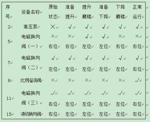
Table 1 performance status of main components of hydraulic systems
3 effects of adaptation
After six months of work, the rehabilitation of two mills was successfully completed. The rehabilitation of the latter two grinding systems has been smooth, resulting in the removal of fabrics and the elimination of the need for on-site man-made fabrics, improving the working environment of workers and reducing their labour intensity. On startup, the milling can rise to the set height (200 mm, lifting pressure around 6 mpa). The grinding machine is light-loaded, the instant-activated current of the main generator is significantly reduced, the impact and vibration of the grinding and slowing machines are significantly reduced, and the grinding machine level and vertical vibration values are equal to 1. 5 mm/s in the case of the belt. The grinder, the main speed retardator and the main generator were effectively protected. The mill operation has improved significantly, and improvements have been recognized by the owners。