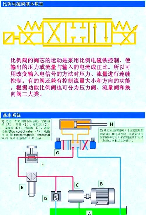
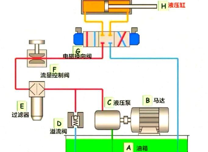
Description of the working principles of the electro-magnetic ratio of hydraulic valves
Scale electromagnetic
There have been repeated references to the importance of the ratio valve in the driving control area - the electrical-mechanical converter that converts the telecommunications signal to a positional shift.
The most important of the alleged parameters in the hydraulic control system are pressure and flow, while the most fundamental means of controlling these two parameters is control of flow resistance. It is the use of a viscous fluid of a fluid medium sensitive to telecommunications, a viscous hydraulic fluid, to convert the electron viscosity to the purpose of controlling current resistance and achieving pressure and flow control of the system ... It is clear that this mode of drift control is simpler and does not require electrical-engineered components ... But at present this technology has not reached the operational stage and requirements.
Controllable flow resistance structures that are currently technically achievable are in the form of indirect electrical-liquid conversion through electric-mechanical converters. This electro-mechanical converter is one of the key components of the electron scale valve. It's the function of converting a proportional flow of input signals into mechanical quantities.
Depending on the object under control or the hydraulic parameters, the force is either passed to a spring of the pressure valve, pre-compressed, or the output force, the force rectangular is compared to the spring, resulting in a small shift or turning point proportional to the current, manipulating the core of the valve activate, and thereby alter, the controllable flow-retarded fluid. It is visible that the electromechanical converter is the driver of the electron scale valve. Its static, dynamic properties play an important role in the design and performance of the entire scale valve.
Electrical-mechanical converter classification
Depending on the principles of its operation and the characteristics of its magnetic system, the main features are:
Electromagnetic, sensory, electric, electromagnetic, permagnetic, polarized; motion circles, kinetic iron; direct flow, communication ...
In terms of their structure and performance, the main features are:
Switched electromagnets, proportional electromagnets, motors, motors, motors.
Scale electromagnetic
This design belongs to a large category of electron scale valves, and the electro-mechanical converter used by name should be the proportional electromagnet.
The function of the proportional magnet is to convert the telecommunications out of the proportional control amplifier into force or transposition.... The proportional magnet is very strong, structurally simple, has low cleaning requirements for the fluid, is easy to protect, has low money, the cortex can be used as a high-voltage-resistant structure, is an electro-mechanical conversion device that is widely used in the electron ratio control element.... The properties of the proportional magnet and the work-reliability of the electron ratio control system and the performance of the components are of great importance and are critical components of the electron ratio control system
Classification of proportional electromagnets
The types of proportional electromagnets are divided into the following categories according to the method of work:
(1) power control type
Such electromagnets have a short travel schedule, a positive ratio of output power to input currents, and are commonly used at the lead control level of the scale valve
(2) process control type
Composed of a power-control load spring, the power of the electromagnetic output is converted from the spring to the output position, which is proportional to the input current, with a work schedule of up to 3 mm and good linear and can be used on the direct control scale valve
(3) location reconciliation
When the position of the cortex is detected by the sensor, it sends a signal of reaction within the valve, re-regulating the position of the cortex within the valve, forming a closed ring control inside the valve, with a high degree of precision, and the position of the cortex having no power. The high ratio valves, such as bosei in germany, atos in italy, etc., use this structure.
Proportional electromagnetics required
(a) be of a horizontal sorption character, i. E. The mechanical strength of the output is proportional to the size of the telecommunications number, not related to the transfer of the cortex, and is capable of proportionately and continuously converting the electrical signal into a mechanical output to the hydraulic valve
(a) sufficient output and itinerary, compact structure and small size
Good linear, small dead zone, high sensitivity
(b) dynamic performance and speed of response
The temperature rise of the ratio valve in long-term work shall not exceed the requirement ... To stabilize work at permitted temperature rises
(a) be able to withstand the high pressure of hydraulic systems and be resistant to interference
These requirements are difficult to meet in many cases at the same time, and should be considered in the context of specific applications ... In some applications, the effectiveness of the output and the itinerary are most important.
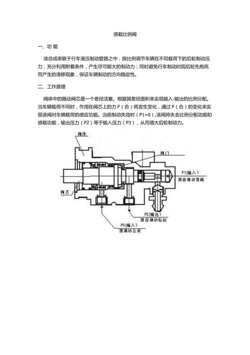
Structure of proportional electromagnetics
The proportional electromagnetic structure is as above. It consists of wires, cortex, pushers, shells, etc.
When there's a signal in the loop, the magnetic field in the circle is active on the cortex. Move in the magnetic field proportionally to the size and direction of the signal current, continuously, and then drive the pusher through a combination of nails to control the movement of the slide valve core.
Proportional electromagnet one power transfer
The proportional magnet is a wet, straight electromagnetic magnet, and the normal electromagnetic switch to the valves requires only two positions of adsorption and disconnection, and, in order to increase the electromagnetic attraction, there are virtually no air gaps in the magnetic circuits, while the proportional magnets are specially designed to form special magnetic circuits, based on the electromagnetic principle. This magnetic route must ensure a certain air gap in the working position of the cortex in order to acquire the fundamental insulation properties, i. E. Horizontal shift-force properties, capable of producing a mechanical mass (power or power rectangulars and shifts) that is independent of the cortex shift, but proportional to the size of the input telecommunications number (electric current). This horizontal power then continuously controls the location of the hydraulic valve core, thus achieving continuous control of the pressure, direction and flow of the hydraulic system. Because the proportional magnets can obtain different forces (or processes) under different currents, pressure and flow can be altered without any degree. The rationale is shown in the following figure:
Proportional electromagnetic properties
Proportional electromagnetic electromagnetic electromagnetic qualifications
The proportional electromagnetic magnetic route is divided into two parts near the working air gap, one of which runs along the axis into the extreme boots, generating the side power fm1 and the other which goes through the diameter gap into the front end of the guidance frame, producing the additional force of the axis fm
"the combination of the two results in a horizontal shift of the proportional electromagnetic-power properties. This particular form of magnetic circuit is formed mainly by the use of an inter-magnetic chain structure, which forms a pelvis of polar boots with cone surroundings.
Proportional electromagnetic current first power
Since the proportional magnet used in this design is a power control type, the cortex of the proportional magnets changes the current of the control wire during the active area of the journey to adjust the size of the output electromagnetic force. As a result of the setting of the current negative reaction link in the scale amplifier, even magnetic resistance can keep the electromagnetic force constant when the fixed current value remains constant. ... The following figure is for the corresponding current first-force characterization curve.
Figure electro-magnetic electro-impact characterization curve
Analysis of performance indicators for comparison valves
Static performance indicators
When the input flow of the demurrage cycling between positive and negative values, the difference in the input current corresponding to the same output value (pressure or flow) is usually specified as the maximum value of the margin and the percentage of the rated current is the demurrage error of the electron prop valve. The smaller the demurrage error, the better the electron ratio is static, the greater the degree of demurrage is generally allowed to be 7%.
Linear ranges and linear degrees are used to ensure that the flow or pressure of the output of the electron scale valve is proportionally altered to the incoming current, and the scope of work of the pressure one current, flow one current, is generally taken to the approximate line of the characteristic curve, which is referred to as the linear range of the electron ratio valve. Linearity is the percentage of the maximum shift of the characteristic curve within the linear range relative to the rated input of the current
, at which time the linear valve shall be selected with a broad and small linear range.
When the flow or pressure of the resolution scale valve is slightly altered (q or p), the minimum amount of the required input current relative to the percentage of the rated input stream is referred to as the resolution ... The resolution is small, the static performance is good, but the resolution is not too small, so does it destabilize the work of the valve.
Repeated accuracy repeats the current at a pressure or flow, and the maximum margin of repeated input and the percentage of rated input are referred to as repeat precision. The smaller the accuracy, the better.
Dynamic performance indicators
The step response is called step time when the input current is given for step signal, the pressure or flow of the output reaches stable state, and its size reflects the sensitivity of the proportional valve action. The step time should normally be less than
"45s. "stabilization means the condition of an output signal exceeding 98% of the adjusted value.
Frequency response: output and re-entry in a stable state when participating in a sine disturbance with a frequency of 3
The ratio relationship is called frequency response. The frequency response definition of the electron ratio valve is increasing for -3db. Marriage
The greater the frequency, the better the performance of the valve, the greater the azimuth
Conclusions
The electron ratio control technology is a late start, but it is very rapid and applies a fairly wide range of integrated electromechanical technologies. Today, electron ratio control technologies are being applied in industry with a range of advantages, are becoming an important option for users in the design of new systems and in the adaptation of old equipment, and have played an important role in raising the level of technological expertise and whiteaction of equipment in enterprises.
One of the trends in electron ratio control techniques is the close integration of electron-supplied technologies with so-called electron-supplied technologies.
One of the most important trends in the industry today is the integration of machines, power and liquids, with the corresponding integration of electromechanical and liquid technologies reaching the level of a country's combined national capacity, or even defence power, which, if not recognized and given high priority, countries will rapidly fall behind in this field and may fall into a downward spiral in future combined national power.
Xxx robotics technology ltd. 0xx