I. Understanding dual-line sensors
There is a general industrial need to measure various types of non-electrophysical quantities, such as temperature, pressure, velocity, angles, etc., and to convert to analogue mass telecommunications in order to reach control rooms or display equipment several hundred metres away. This equipment, which converts physical volumes into telecommunications numbers, is called a transporter. The most widely used industrially is the use of 4-20ma currents to transmit simulations。
The reason for the use of current signals is that they are not easily disrupted. Also, the currents are inexhaustible, and the conductive circuits do not affect accuracy and can be transmitted hundreds of metres on the ordinary double winch. The upper limit of 20ma was taken because of the blast-proof requirement that the spark energy caused by the power outage of 20ma was insufficient to ignite the gas. The reason that 0ma was not taken from the lower limit was to detect the breakline: normal working hours were not less than 4ma, and when the transmission line was broken due to malfunction, the circulation of the circuit was reduced to zero. Commonly takes 2ma as a breakline warning value。
The currenter converts the physical volume to 4-20 ma current output, which must be supplied by external sources. Typically, the carrier requires two power lines, plus two current-output lines, to be followed by a total of four lines, known as four-line transformers. Of course, current output can be a line shared with the power source (public vcc or gnd) and saves a line, known as a three-line transducer. In fact, it may be noted that the currents of 4-20ma itself can provide power to transformers, as shown in figure 1c. The transformer is equivalent to a special load in the circuit, with the special feature that electrical currents of the transformer vary between 4-20 ma depending on the sensor output. The display instrument only needs a string in the circuit. Such a transducer would require only two lines and would therefore be called a two-line transducer. The industrial current circulation standard is limited to 4ma, so that the transmitter is at least 4ma in the range. This makes it possible to design dual-line sensors。
In industrial applications, measurement points are generally on site, while displaying equipment or control equipment is generally in the control room or cabinet. The distance between them could be tens to hundreds of metres. At a 100-metre distance, saving two lines means cutting costs by almost $100! Therefore, dual-line sensors are necessarily the preferred in application。
Ii. Structure and rationale of the dual-line transporter
The principle of a two-line transducer is to use the 4-20 ma signal to power itself. If the carrier itself consumes more than 4 ma, it is not possible to output a lower limit of 4ma. Therefore, it is generally required that the two-line transformer itself (all circuits including sensors) do not consume more than 3. 5 ma. This is one of the fundamental principles of the design of a two-lined transducer。
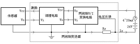
In terms of the overall structure, the two-line transformers consist of three main components: sensors, circuits, and two-line v/i transformers. The sensor converts the physical amount of temperature, pressure, etc., into electrical parameters, and adjusts the circuits to magnify, adjust and convert the small or non-linear telecommunications out of the sensor into linear voltage output. The dual-wire v/i transform circuits control the overall power consumption based on the output of the signal-adjusted circuits; at the same time, voltage and voltage are obtained from the loops for the management of circuits and sensors。
With the exception of v/i transform circuits, each part of the circuit has its own power-consuming currents, and the core design idea of the two-wire transformer is to include all currents in the v/i conversion feedback loop. As illustrated, sample resistance rs is at the lower end of the circuit, and all currents are returned to the negative pole of the power supply through the rs current. The feedback from rs contains electricity consumption on all circuits。
In dual-wire transformers, all circuit power cannot be greater than 3. 5 ma, making the low utility of circuits the main design difficulty. The rationale and design elements of each segment of the circuit are analysed below。
Iii. Double-line v/i converter
V/i converters are circuits that control the output of currents with a voltage signal. The dual-line v/i converter is at different points from the general v/i transformer circuit: the voltage signal does not directly control the output current, but controls the entire circuit itself. At the same time, steady voltage will be extracted from the current circulation road to provide power to adjust circuits and sensors. The following is a two-line map of the basic principles of the v/i conversion circuit:
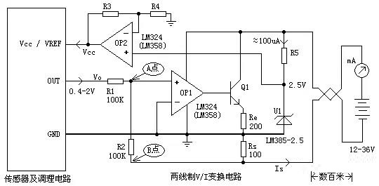
Figure op1, q1, r1, r2, rs constitute v/i converters. Analysis of negative feedback processes: if point a is higher than 0 v for some reason, the delivery of op1 output rises, the two end ends of re rises in voltage, and the currents increase through re. Equivalent to overall power consumption, the current of resistance to rs by sampling has become larger and the b point voltage has become lower (negative). As a result, point a voltage was pulled down through r2. On the other hand, if point a is below 0v for some reason, it is also pushed back by negative feedback. In summary, negative feedback resulted in the release of op1 short, a point voltage = 0v. Below is an analysis of vo's control principles for total electricity consumption:
Assuming the circuit output voltage is vo, the current runs through r1
I1 = vo/r1
It's impossible to absorb currents at the drop-in end, and i1's all flowing through r2
Vb = -i1*r2 = -vo*r2/r1
R1 = r2 with vb =-vo
Only rs and r2 were held between the negative power supply and the entire portable circuit, so all currents passed over rs and r2. The upper end of r2 is false (0v) and the upper end of rs is gnd. So r2 and rs are identical and equal to vb. Corresponds to rs being combined with r2 as a current sample resistance. So total electrical current:
Is = vo/(rs/r2)
If r2 > rs, is=vo/rs
So, in figure 3, we take rs = 100 euros, and when adjusting circuits for the output of 0. 4 to 2 v, total electricity consumption is 4 to 20 ma.
If r2>rs cannot be satisfied, rs and r2 are fixed, and is and vo remain linear, and the error factor can be eliminated on time。
In addition to the correct circuit, two conditions are required for normal operation of the circuit: firstly, to keep its own electricity as low as possible, and firstly, to supply the saved currents to fix the circuits and transformers. The second requirement is that the discharge be able to work on a single source, i. E. In the absence of negative power, the input end is still able to accept zero v input and function normally。
Lm358/324 is the most common and lowest-priced single power source, 400ua/per discharge, which is generally acceptable. When power is provided by single power source, the input end works from the range -0. 3v ~vcc-1. 5v. If the precision amplifier, such as op07, is replaced by a precision amplifier, as input is not allowed to be as low as 0v, it is not possible to work in the circuit。
R5 and u1 constitute the baseline source and generate 2. 5v stable baseline voltage. Lm385 is a low-cost micro-energy benchmark that can work at more than 20ua, and the curve given in the manual is the flatest near 100ua, so it is about 100ua controlled through r5. Op2 forms a homogenous amplifier that expands the baseline and provides power to adjust circuits and sensors. Because of the scarcity and cost of broad input voltage and low-capacity pressurers, benchmarking is a cheap option。
This part of the circuit may also select an integrated circuit available. For example, xtr115/116/105, which is more accurate and stable than homemade, and has lower self-utilisation (means that more electricity can be left to fix circuits and that it is easier to design). But the cost is more than 10 times higher than that.
Iv. Design of two-linear pressure transformers
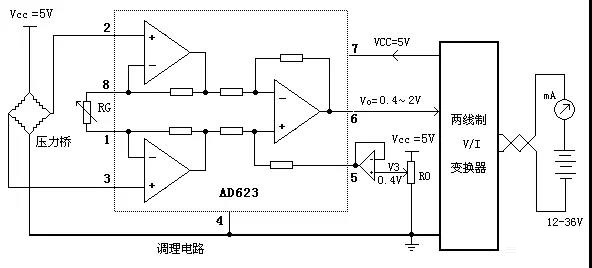
The pressure bridge, or mass sensor output signals are weak and are of the mv class. Small signals of this type typically require a first-level magnification with a differential amplifier. Low disorders, low temperature transport differential amplifiers are commonly selected. It is also necessary in dual-line applications. Ad623 is a commonly used low-capacity differential amplifier, which is often magnified at the front level of the differential output. The ad623 disorder has a maximum of 200 uv and a temperature transport of 1 uv/degree, which ensures sufficient accuracy in general pressure transport applications。
R0 adds 0. 4v superimposes to the ref foot (5 feet) of ad623, and by adjusting r0 to output 4ma under pressure = 0, then adjusts rg output 20. 00ma and completes calibration。
In the design of circuits, care needs to be taken that the pressure bridge sensor is equivalent to a 1,000-eu class of electrical resistance, which generally consumes more electricity. An appropriate reduction of the pressure bridge's incentive voltage can reduce electricity consumption. However, the output range has also declined, requiring an increase in ad623. The sensors shown in figure 6 are powered by constant pressure, and most semiconductor pressure sensors in practical applications require constant current power to acquire better temperature properties, which can be stimulated by a discharge that constitutes a constant flow source。
V. Stability and security considerations
Because of the harsh environment and high reliability requirements in the industrial environment, dual-line transporters need to be designed to take into account certain conservation and stability measures。
Power protection。
Back-up, over-pressure and surges of power are common problems in industry. The power supply is, in turn, the most likely error to occur when the equipment is installed, and the entry of a diode in the mouth chain prevents damage to circuits when the power is taken back. If the input end is accompanied by a full-bridge integrator, then even the power supply will work。
In order to prevent energy damage to transmitters such as lightning strikes, static discharges and wave surges, a tvs tube can be installed at the portal to absorb instant excess energy. General tvs voltage values are slightly lower than discharge limits to protect. If lightning strikes are possible, tvs may not absorb enough capacity, and pressure-sensitive resistance is necessary, but the charge-sensitive resistance itself causes some error。
Overflow protection。
There may be errors in the operation of the equipment, such as sensor break-ups, short circuits, etc. Or the input volume itself is likely to exceed the range, and the carrier must ensure that the output does not rise indefinitely under any circumstances, otherwise there is a risk of damage to the carrier itself, the power source, or the remote display instrument。
The figures for rb and z1 constitute excess protected circuits. Whatever the reason for the output of op1 greater than 6. 2 v (1n4735 is 6. 2v pressure tube) is the z1 position, and the base pole of q1 cannot be higher than 6. 2 v. Therefore, it is unlikely that the voltage on re will exceed 6. 2-0. 6 = 5. 6 v, so that the total current will not be greater than ue/re = 5. 6v/200 = 28ma。
3. Wide voltage resilience。
A general two-line transporter can adapt to large-scale voltage changes without affecting accuracy. This allows for the application of all types of power supply, while being able to adapt to large load resistance. The most sensitive part of the power supply is the baseline source, which is the main element determining accuracy. The baseline in the 3rd floor map passes through the r5 limit, and when the power voltage changes, the current on the r5 also changes, with significant implications for the baseline stability. The use of the constant current source lm334 as the baseline for power generation in the attached figure ensures the stability of the baseline when large-scale voltage changes occur。
4. Power withdrawal
In general circuit design, each integrated circuit has a retortion at its source. When the two-lined transformer is powered, the charge of these capacitors causes a large electrical current in an instant, with the potential to damage remote instrumentation. Thus, each retort normally does not exceed 10 nf and the total retorture should not exceed 50 nf. A 10nf capacitor at the entrance is necessary to ensure that the circuit is not convulsed by long line sensory loads。
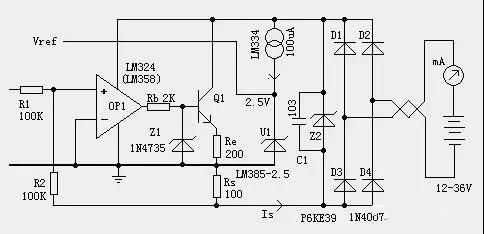
5. Double-line v/i converter (map)