I. Common sensor base knowledge
Sensor is defined as: “a device or device capable of being measured and converted to a usable signal according to a certain pattern, usually consisting of sensitive and transformation elements”. Sensors are a detection device that can feel the measured information and can regularly transform the information felt by detection into a telecommunications number or other form of information output required to meet the requirements of transmission, processing, storage, display, recording and control of information. It is the primary link in achieving automatic detection and control。
Classification of sensors
There are currently three types of sensors that are more commonly used:
Categorized by the physical mass of the sensor, which can be divided into sensors such as place transfer, force, velocity, temperature, flow, gas composition, etc。
Categorized according to the principles of the sensor's work, it can be classified as a sensor such as electrical resistance, electricity, electrons, voltage, hall, photovoltaics, rasters, thermoelectrics, etc。
Categorized by the nature of the sensor's output signal, can be classified as: a switch sensor with an output of a switch volume (“1” and “0” or “on” and “on” and “on” or “on”); an output with an analogue sensor; and a digital sensor with an output of pulse or code。
Classification of sensors
1 based on measured physical weights: e. G. Force, pressure, shift, temperature, angle sensor, etc。
2 in accordance with the working principles of sensors: e. G., mutation sensors, voltage sensors, pressure-resistant sensors, electro-sensors, capacitor sensors, photovoltaic sensors, etc。
3. Subdivision of energy by sensor:
(1) energy conversion type: e. G., voltage, thermal voltage, pv sensors, etc。
(2) energy control types: e. G. Electrical resistance, electro-sensors, hor type sensors, heat-sensitive electrical resistance, photo-sensitive electrical resistance, wet-sensitive electrical resistance, etc。
4. According to the sensor's working unit:
(1) structure type: e. G., electro-sensor, capacitive sensors, etc。
(2) material types: e. G. Voltage, photovoltaic, semiconductor sensors, etc。
5. Form fraction by sensor output signal:
(1) simulation: sensor output is simulated voltage。
(2) digital mode: sensor output is a numerical amount, e. G., encoder type sensor。
Iii. State characterization of sensors
The static properties of the sensor are the input signals of the static and the correlation between the output and input of the sensor. Because the amount of input and output is not related to time, the relationship between them, i. E. The static properties of the sensors, can be described by an algebra equation that does not contain time variables, or by cross-coordinates of the input amount, drawing the characterization curves that correspond to the output. The main parameters for the static properties of the expression sensors are linearity, sensitivity, resolution and delay。
Iv. Dynamic properties of sensors
Dynamic properties are the characteristics of the sensor's output at the time of input change. In practice, the dynamic properties of sensors are commonly expressed in its response to certain standard input signals. This is because the sensor's response to a standard input signal is easy to obtain by experimental means and there is a relationship between its response to a standard input signal and its response to a random input signal, which is often understood to be presumed. The most commonly used standard input signals are both step-to-step and sine signals, so the dynamic properties of sensors are also commonly expressed as step-to-step and frequency responses。
Linearity of sensors degrees
Typically, the actual static characteristic output of the sensor is a bar curve rather than a straight line. In practice, in order for the instrument to have a balanced reading, a linear line is commonly used to approximate the actual characterization curve, linearity (non-linear error) as an indicator of this approximation。
There are a number of ways to select the line. When a theoretical straight line is associated with a zero input and a full range output point as a proposed straight line, or it is proposed to be aligned with a square and minimal theoretical straight line of deviations between points in the characteristic curve, this line is referred to as the smallest two-multiplier method。
Vi. Sensor sensitivity
Sensitivity is the ratio of a sensor's output change y to input change x in a steady state of operation。
It is the slope of the output one input feature curve. S sensitivity is a constant if there is a linear relationship between the output and input of the sensor. Otherwise, it will vary depending on the input volume。
Sensitivity is measured as the ratio of output to input. For example, an output voltage change of 200 mv at 1 mm is expressed as a sensitivity of 200 mv/mm for a shift sensor。
Sensitivity can be understood as a magnification multiplier when the sensor's output, input size and scale are the same。
Increased sensitivity allows for higher measurement precision. However, the higher the sensitivity, the narrower the scope of the measurements, the less stable they tend to be。
Vii. Late properties of sensors
The degree to which the delayed feature expression sensor is not consistent between the positive (increased input volume) and the reverse (reduced input volume) processes - an input characterization curve is usually expressed as a percentage of the maximum margin between the two curves max and full range f. S。
Delay can be caused by the absorption of energy in the inner element of the sensor。
Resisting sensors are a device that will be measured, such as transposition, shape transformation, force, acceleration, humidity, temperature, etc. There are mainly resistance sensors such as electrical resistance variants, pressure resistance, thermal resistance, heat sensitivity, aerobic sensitivity and wet sensitivity。
Resistor variant sensors
The electrical resistance transformers in the sensor have metal reactive effects, i. E. Mechanical transformations resulting from external forces, resulting in corresponding changes in electrical resistance values. Resistors are mainly in the metallic and semiconductor categories, with metallic filaments, gills, thin membranes. Semiconductors have the advantage of being highly sensitive (usually a few dozen times the silk, argon) and having small horizontal effects。
Pressure-resistant sensors
Pressure-retarded sensors are devices based on the pressure-retarded effects of semiconductor materials that are diffused on the base plate of semiconductor materials. It can be directly used as a measuring sensor element, spreading resistance into the form of a bridge within the base. When the plate is shaped by external forces, the resistance values change and the bridge produces the corresponding imbalanced output。
The material used as a pressure-resisting sensor (or film-resisting film) is mainly silicon and oscillating. Silicon pressure-resisting sensors made of sensitive materials are increasingly valued, especially for solid-state pressure-resisting sensors that measure pressure and speed。
Thermal resistance sensors
Thermal resistance sensors measure temperature and temperature-related parameters using the characteristic of resistance values that vary with temperature. This sensor is more applicable in situations where temperature detection accuracy is higher. Thermal resistance materials, which are now more extensive, are platinum, copper, nickel, etc., which have characteristics such as high resistance temperature coefficients, good linearity, stable performance, wide range of use and ease of processing. For measuring temperature in the range -200°c ~ +500°c。
Hall sensor
Hall sensors are magnetic sensors based on the hole effect. Place an object with electrical currents in a magnetic field. If the current direction is vertically related to the magnetic field, horizontal bit differentials occur in the direction of both the magnetic field and the current direction. This phenomenon is known as the hole effect, and the resulting level differential is known as the hole voltage。
The hole device is made of semiconductor materials that produce a significant hole effect. As an electromagnetic conversion element in the hole sensor, it can be used for electromagnetic measurements, such as measurement of magnetic fields, currents, electrical power, magnetic physics and electricity. Hall sensors can also use magnetic fields as media to achieve non-contact measurements of many physical volumes。
The conversion of non-electricity, such as power, transposition, vibration, acceleration, speed, flow, etc., is widely applied in the fields of industry, transport, communications, automatic control and household use of electrical appliances。
According to the function of the hole device, they can be divided into: hall linear and hall switches. The former output analogues the latter output numbers。
Their application can be divided into direct and indirect applications, depending on the nature of the object being tested. The former directly detects the magnetic field or magnetic properties of the object itself, while the latter is the magnetic field that detects the artificially configured magnetic field on the subject to be used as the vector of the detected information, through which many non-electric, non-magnetic physical volumes, such as force, force rectitude, pressure, stress, position, position, movement, speed, acceleration, angle, angle speed, turn, speed and time of change in the working state of the subject, are converted into electrical quantities for detection and control。
The horware is divided into two categories: the hole component, which is a simple hole film, and the hole integrated circuit, which is often used to magnify the available hall voltage. The latter integrates the hall and its signal processing circuits on the same chip。
Hole components can be made from a variety of semiconductor materials, such as ge, si, insb, gaas, inas, inasp and multilayer semiconductor isometric quantum quail materials。
Hall switch circuit
The hal switch circuit, also known as the hole digital circuit, consists of a voltager, a hall tablet, a differential amplifier, a smith trigger and an output level. Under the action of the external magnetic field, when the magnetic induction strength exceeds the threshold of the guidance bop, the hole circuit output tube is conduited to produce low electrical level. After that, b was added and remained conductive. When the b value of the magnetic field is lowered to brp, the output pipe is closed and the output is high. We call bop the work point, brp the release point and bop-brp = bh the return difference. The presence of reversibility increases the resilience of the switch circuits. The functional box of the hal switch circuit is shown in figure 4. Figure 4 (a) refers to the oc output and (b) to the double output. Their output characteristics are shown in figure 5 and figure 5 (a) indicates the normal hall switch and (b) indicates the locked hall switch output properties。
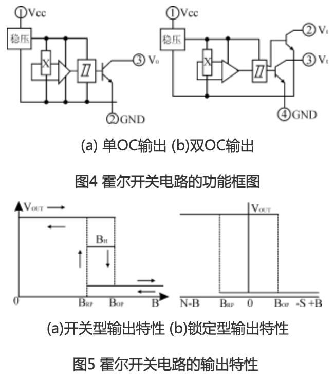
It is generally stipulated that when the extra-magnetic antarctic (s pole) approaches the marked side of the hull, the effect of the magnetic field on the hull is positive and the arctic is negative when approaching the mark。
The lock-in hal switch circuit is characterized by the fact that when field b is increasing and reaching bop, the circuit is connected, and then, regardless of whether b is increased or reduced, or even b is removed, the circuit remains transient, and only when the negative brp is reached, it is called the locking pattern。
General problems with hall application
(1) measurement of the magnetic field
The method of detecting the magnetic field using the hole device is extremely simple, and the hor device is placed as a kind of probe, which, because it is sensitive only to the magnetic intensity of the surface vertically to the hale tablet, must be applied vertically to the surface of both the magnetic line and the device, which can be obtained by the output voltage. If not vertical, a vertical fraction is obtained to calculate the magnetic induction strength of the measured magnetic field. Moreover, because of the small size of the hole element, multi-point testing can be performed, computer data processing can be performed, the field can be distributed and the magnetic field can be detected in narrow, small holes。
(2) settings for working magnets
When a magnetic field is used as a motion and position information vehicle for a sensored object, permanent magnetic steel is generally used to produce a working magnetic field. For example, using a 5x4x2. 5(mm3) cylindrical radon ii magnetic steel, the magnetic polar surface of which can be obtained with a magnetic induction strength of approximately 2300 goss. Magnetic sensitivity decreases rapidly with distance in the airspace. In order to ensure the reliable operation of the hole device, especially the hall switch, the application should take into account the length of the effective working gap. In calculating the overall effective working gap, it should start from the surface of the horticultural tablet. In the sealed hale circuit, the depth of the hale film is given in the product manual。
Since the hole device requires a working power source, the general magnetic body moves with the detectable object during motion or position transfer, holding the hole device at the appropriate location of the work system, using it to detect the work magnetic field and extract the inspected information from the results。
(3) interface with external circuits
The output level of the hall switch circuit is typically an npn transistor with the same rules as any similar npn switch. At the end of the output tube, the leaking stream is small, usually only a few nas, and it is negligible that the output voltage is close to its power voltage, but the power voltage does not exceed the penetration voltage (i. E. The maximum voltage specified in the norm sheet). When the output tube is channeled, its output end and line are short-circuited to the public end. Therefore, an electrical resistor (i. E., a load retardant) must be replaced to limit the current through the tube to a maximum permissible value (usually 20 ma) to avoid damage to the output tube. When the output current is larger, the saturation pressure of the tube increases, and users should pay particular attention to the compatibility of this only with the cut-off voltage (or logic “zero”) of the circuit under your control。
(4) no brush in direct current medium
The direct-flow unbrusher uses the constant magnetic rotor to place the required amount of the horde ss1350 at the right position of the berth, whose output is linked to the corresponding fixed circuits. When the rotor passes through the vicinity of the hor device, the magnetic field of the permagnetic rotor emits a volley with a voltage voltage that gives the fixed circuits power, creates the same magnetic field as the transmagnetic field, and pushes the rotor to continue to move. To the next position, the former location of the hole device ceased to function and the lower location of the hall device was steered so that the next round was powered, creating a push field to keep the rotor moving. So cycle, keep the power working。
Here, the hole device acts as a location sensor, detecting the location of the rotor magnet pole, its output disrupts the fixed circuit around which the electricity is supplied, and it acts as a switch. When the rotor lode departs, it suspends the work of the previous hale device, and the next one starts, so that the rotor magnetosphere always faces the magnetic field, and the hale device acts as a fixed current switch。
Hole devices without a brush can be used either with a hole component or with a hall switch. When using the hole component, the circuits are typically magnified externally, using the hall switch circuit, which drives the circuits directly around the circuits, making them much simpler。