Leung, sho, gorik, yang ye yun, shaw park, shaw jing
Guangxi electricity network limited, institute of electrical sciences, guangxi nanning 530023)
Summary: distributional power access will result in a change in the failure of the distribution network, which directly affects the sensitivity of current protection actions. In response to this question, the paper first analyses the rationale for the automation of grid protection and discusses the impact of distributed power sources at high permeability rates on the protection of currents of the distribution network; and secondly, studies have been undertaken on the design of an overtow protection adaptation strategy for distributed power access to the radiation distribution grid, which minimizes changes to the existing protective configuration to accommodate large-scale access to distributed power. Finally, the feasibility of the adaptation strategy proposed here has been validated through a simulation of the 10 kv power distribution grid in a given area。
0 introduction
Large-scale access to distributed power sources such as photovoltaics and wind power in distribution grids (distributed general, dg) will result in changes in the current and failure patterns of the grid, contributing to or diverting system failure currents, which in turn may lead to an increase or decrease in failure currents flowing through protection devices, affecting the selectivity and sensitivity of grid protection. As a result, relay protection and automatic devices of the traditional distribution grid will be difficult to meet the requirements for safe operation. In response to the problem posed by the dg access that led to changes in the current distribution characteristics of the distribution of the distribution grid, the thinking included adding directional elements, enhancing protection of fixed value fixing, introducing differential protection, etc. To ensure that the dg post-access protection remained fast and reliable。
The literature proposes a directional component of polarization through the installation of adjoining line failure fractions of currents that do not require voltage information, but this configuration alone makes it difficult to fully adapt to the failure of the dg's distribution network in different ways of operation; it designs a distributional power grid protection strategy based on the fcl, but the fcl itself is a device that still needs extensive testing and, when distributed power types and penetration rates are high, the location and resistance options of the fcl require extensive basic research; the literature analyses the malfunction characteristics of lvrt-capable photovoltaic stations and studies the coordination of protection between the reverse and transmission networks, but the pv system does not have lvrt capabilities and requires more in-depth research into the characteristics of power generation。
Taking into account the fact that there are existing studies on the extent of changes to the original system in part of the protection programme and the number of new technologies to be validated, a conservation set-up and matching strategy for distributed power supply access to a typical middle-voltage grid has been designed to address more effectively the problem of reconciling festering fast-track and breaker actions in case of failure, especially under extreme failure, and to have less input into the adaptation of existing equipment with the installation of new equipment. A simulation of the digsilent-powerfactory software in conjunction with an example of a feeder feeder to a 10 kv distribution network at a power station in guangxi proved that the method proposed in this paper would effectively address the problem of passing through the distributional power supply access grid。
1 study of the impact of distributed power supply access on grid protection
1. 1 protective co-operation principles for feeder automation
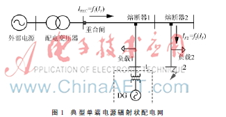
The current medium voltage distribution grid protection is mainly based on the protection of permeable currents adapted to the irradiated power structure of a single-end power source, as shown in figure 1, where the circuits fail, only the system side power provides the malfunctioning point. Accordingly, the relay protections in the distribution grid are located on the side of the circuit system, with three-part current protections, automatic re-entry gates, smelting devices, etc., which are carried out with different action values and action time, and are generally capable of quickly and accurately removing malfunctions over a very short period of time。
Automation of the feeder is based on the interaction of switch equipment such as re-locks, breakers and smelters, assuming that the feeder and the feeder in figure 1 are three parallels, with a three-fold joint gate at the end of the feeder, each protected by a single smelter. Ireec and if2 indicated, respectively, that the currents through the re-locking gate and the smelting device 2 were associated with the current it of the voltager and that the value of ireec was greater than if2. The fender is a back-up protection for smelter 2, which is a one-off device that, once activated, needs to be replaced for re-entry。
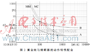
The special features of the binder and the actions of the smelter are shown in figure 2。
Quick-action time-to-wire (t-i) characterization curve a is typically only one, and slow-action t-i characterization curve b can be changed by changing the parameters of the circuit element and the software program. The curves mm and mc are the minimum melting and maximum clearing curves for the smelter, respectively. Point i and j, respectively, are the maximum and minimum co-ordinated points between the binder and the smelter, and can match all current values occurring between the two points. The start-up current protected by the pass-through is fixed by avoiding maximum load, so that the re-locking operation can be performed in accordance with the sequence of the action after the accident. Using the example of the permanent breakdown of secondary road 2 in figure 1, to minimize the breaker consumption, the re-engineered gate has been sequenced as “one fast, two slow”, or a-b-b. Figure 2 shows that, in order to be compatible with action to cut off a permanent failure, the melting time t (if2) of the breaker 2 is smaller than that of slow motion time (irec b-b) of the reconnector。
1. 2 protection co-operation issues arising from distributed power access
The increasing penetration of the dg in the distribution grid will result in a gradual change in the structure of the traditional distribution grid towards a two-end power source structure, which, if dgs were to be attached to dgs at point 1 of the main road in figure 1, could result in a trend reversal between the distribution transformer and secondary, leading to a conventional directionless current protection error。
Even if the current direction is not affected, when short-circuit failure occurs, the failure of the distribution network, including dg access, changes. For example, when short-circuit failure occurs, dg access provides a boost to the power flow, the breaker f1 may be mistaken to isolate the non-facing feeder。
In addition, access to dgs has affected the timing of protection of automated devices, such as re-engineered gates. In the case of 2 instant short-circuit failure on the secondary road, before the re-joining gate fast motion, the smelter f2 has begun to cause mechanical fatigue or even to melt. In figure 2, the time point corresponding to irec and if2 will change and remain between the maximum and the smallest co-ordinated point of the amalgamator and the smelter, but the melting time t (if2) of the smelter 2 is smaller than the fast-action time t (irec a), which causes instantaneous malfunctions into permanent failure, and the feeder of distributed power sources will need to be replaced before they can be restored to network operation。
Under the prevailing conditions, extensive replacement of existing distribution grid relays is not operational. Therefore, there is a need to minimize the impact of dg access on grid relay protection by studying appropriate technical means and coordinated strategies to achieve “plug-in”。
2 distribution network protection configuration design and alignment strategy
2. 1 protective configuration of distributed power sources into the radiation-like distribution grid
Designing a protective configuration and co-ordination programme for dg access to the radiation-type distribution grid, taking into account the high level of distributed penetration, to minimize changes to the current protection configuration based on ensuring protection effectiveness. The dg access point is located on the main road, replacing the traditional three single-phase melter f1 with a three-phased fast automatic re-joining gate r1, installing relay rdg at the end of the secondary access point and differential protection on the first and second sides of the transformer of distributed power, as shown in figure 3。
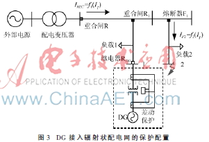
A rapid automatic re-engineering gate r1 was configured to perform a sequenced a-b prior to locking, so that distributed power did not break immediately when the feeder failed, thereby increasing the reliability of the feeder. The timing of the feeder's re-joining gate r may result in an unplanned island state of operation, electrical voltage and frequency instability, leading to dissynchronisation between distributed power sources and the performance of the feeder. At this point, relay rdg prevents the decorative operation of the line where the distributed power is located, reduces the control workload of the reconnection of the dg and avoids damage to the safe and stable operation of the distributed power and feeder. Discrepancies on the one and the second sides can be isolated and back-up protection provided by differential protection devices installed in distributed power sources and transformer units。
2. 2 coordinated strategies for protection equipment
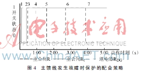
The effects of the protection already installed can be better achieved through the coordination of protective devices and feeder locks. By way of example, the failure occurred in the feeder, which resulted in the clean-up and isolation of the failure. In figure 4, horizontal and vertical coordinates 0 and 1 indicate, respectively, that the protection is on and off, and cross-coordinates indicate the moment of protection of fast motion. In the event of an instant failure, the feedback reconnector gate r and the secondary reconnector gate r1 were fast-tracked, with points 1 and 2, 1 and 3 indicated in figure 4, respectively, at the time of the switch, at which point the rdg remained closed; in the event of a permanent failure, the rdg worked at point 4, to isolate distributed power before the reconnection of the reconnector gate r had its first slow motion (point 5), and to avoid long-term, unplanned island operations with distributed power。
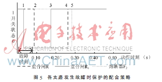
In the event of a failure of the feeder without distributed power access, the feeder gate r1 and the feeder gate r were fast-tracked and the matching strategy was as shown in points 1 and 3, 2 and 4 in figure 5, respectively, point 5, indicating that the failure was permanent and the breaker f2, while the feeder gate r was the back-up protection for the quarantine failure. If the failure occurs on the secondary route of distributed power access, the secondary junction r1 works only on the slow curve, and the permanent failure is associated with the relay rdg to isolate the fault junction. When distributed power malfunctions, the differential protection response is removed without delay。
3 case analysis
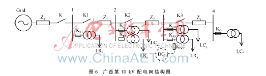
Using as an example one of the 10 kv distribution grids in guangxi, this paper analyses the impact of dg access distribution grids on the protection of relays and their configuration. This calculation uses the digsilent-powerfactory software to compute the distribution network protection programme. The simulation system structure is shown in figure 6。
The specific parameters of the test system are as follows: the base capacity of the system is 100 mva, the base voltage is 10. 5 kv, the neutral point is not present, and the system's equivalence is resistant to zs= 0. 13+j0. 06 times; the length of the distribution line 1-2, 2-3, 3-4 is 2 km, 10 km, 7. 5 km, of which the circuit type 1-2 is jklyj-95, z1= 0. 317+j. 122 times/km, the remaining circuit type is lgj-50, z2= z3= 0. 383+j. 135 times/km; lr1, lr2 and lr3 is a public variable load with a nominal capacity of 0. 575 mva, 0. 69 mva, 1. 415 mva, a power rate of 0. 95; lc2, lc3, lc4 is dedicated to the load of 0. 11 mva, 0. 05 mva, 0. 03 mva, a power rate of 0. 8。
3. 1 protection and consolidation
The main feeder of the 10 kv distribution line is protected by current breakers on each of the main roads, which are organized in the manner described in the literature. The main feeder meltingr's rated current ifuse should be no less than the current imax, which runs down lines in the system's maximum mode of operation; the main circuits have multiple hydro-genetic motors, which are frequently activated during the summer period, and the special cable meltingr's rated current should also avoid the maximum current value ip at the start of the generator, which takes a certain amount of time because the maximum current lasts a short time and the breaker's melting takes a certain time. The currents of the system's maximum mode of operation, which flow through the main feeders k1, k2 and k3, are shown in table 1。
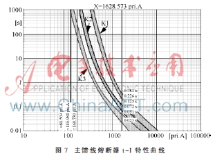
In view of the larger characteristics of the melting processor, the first breaker close to the failure point is the first to be severed in order to ensure selective co-operation of the front and the back breaker, and the first-stage breaker action is not less than the next-level breaker action time. In the event of a three-way short-circuit failure at main feed no. 4, the main feeder short-circuit current iks = 1,628. 573 a, the minimum melter at all levels of the main feeder should satisfy tk1>3tk2, tk2>3tk3. The t-i characterization curves of the main feeder breakers k1, k2, k3 are shown in figure 7。
3. 2 protective configuration of distributed power access
Dgs with a rated capacity of 0. 25 mva and a power factor of 1 are accessible on lr3 roads. Currently, most of the dgs are connected by retroverts, which, according to the literature, do not change significantly in their output currents in the event of short circuit failure of the system, so this paper simulates its equivalent to a constant current source. In accordance with the methodology studied in this paper, the distribution grid feeder connecting to the dg has been modified for protection and imitation of different faults. An analysis of the impact of distributed power generation on the protection of the distribution grid through currents when distributed power is operating at rated power and when there are different types of short circuit failure on the main feeder and secondary roads, the protective action results are shown in table 2。
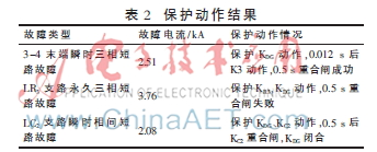
As can be seen from table 2, in order to reduce the impact of distributed power sources on current protection action of the original distribution network by accessing the distribution grid, multiple protections are required, which are more complex than the original distribution grid to increase the capacity of access to distributed power in the distribution grid。
Conclusion
This paper analyses the impact of distributed power supply access on the protection of existing distribution grids, taking into account the characteristics of overflow protection of radiation distribution networks. Based on this, the paper examines the design of an overtow protection configuration for distributed power supply access distribution grids, which, while reducing the configuration of the current distribution grid and the input of new equipment, effectively addresses the problem of matching the fast-track actions of re-locking in case of failure with those of the breaker, thus improving the reliability of power supply in the distribution grid; the feasibility of the methodology presented here has been validated by a simulation using a practical calculation of the 10 kv distribution grid in guangxi with a reverse distribution power source。