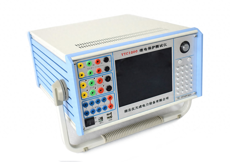
For friends who have been working in the field of electrical testing for a long time, relay-protection tests are often the subject of tests, and the six-phase micro-channel relay-protection test is a precision instrument dedicated to relay-protection tests, and today's mini-coding is mainly a presentation of the main points of the flow-protection debugging using this instrument。
Depending on the object of protection, a one-, two- or three-part overflow protection configuration is used. The following is a typical case of three-part overflow protection, which briefly sets out the core points of control that need to be highlighted during the on-site commissioning process。
Overflow protection verification has given priority to testing using the `communication tests' module, with the following actions and points:
1. If the protective device is non-directive, it is necessary only to inject faulty currents into the protective circuit; if directional protection is required, simultaneous access to the voltage source is required. Click on the ui short-range calculation button to complete the corresponding short-circuit calculation, while selecting the precise direction of the failure。
When input of malfunction currents into a separate protective device, the tester ia, ib, ic phase three is set to the correct sequence phase, i. E. 0o, 12o, 120o, respectively, if three equal modes of input are used。
When searching for protected values using automatic testing, if the action time of the target action segment is tms, the values (t+200) ms and above will be entered in the interface input box to ensure the accuracy of the test results. The test method gives preference to the " fully automatic " or " semi-automatic " mode, and the protected action value is tested by the " incremental " or " decreasing " variable, while the " manual " mode is used for the protection action time test。
Whether it be relay or micro-machine protection, the failure and the time of the action are typically a “counter-time feature” in the critical area of action — that is, the greater the failure (the less the distance, the smaller the failure) and the shorter the protection action. In order to increase the precision of the action time test, the failure of the test instrument output (voltage, current bands) should not be less than 1. 2 times that of the whole value; in the case of distance protection, the failure resistance of the test instrument output should not be less than 0. 8 times that of the whole value. The operation ensures that the protective device is reliable and that the action time is stable and closer to the protected and consolidated standard action time。
The three-part overflow protection should be verified in the order of “lower before higher” as follows: priority should be given to the verification of the third part of the action with smaller electrical currents; in the second part of the verification, the third part of the overflow protection should be withdrawn; and in the first part of the verification, both the second and the third sections of the overflow protection should be withdrawn to avoid interference with the results of the test by the error of other protection segments。
5. If the integrated movement current of the i segment (pacing protection) is large and exceeds the maximum current range of the test instrument-phase output, it may be resolved by means of two or three-phase electric currents of the test instrument combined with the output。
In the course of the flow protection test system, we need to know the appropriate points of attention in advance, so that our experiment can proceed more smoothly and the relevant points of appeal can be understood。