620)this. Width=620; "syle=cursor:point"/
Ii. Hall switches - rationale
The hole effect is that when a current metal or semiconductor thin piece is placed vertically in the magnetic field, the two ends of the thin piece produce a difference in the level of power, the difference of which is known as the hole power u, expressed in the following:
U = kib/d
In formula, k is the hole coefficient, i is the current passed through the thin sheet, b is the magnetic induction strength of the magnetic field and d is the thickness of the thin sheet。
The hall switch, which is an active magnetic converter, is based on the hole effect doctrine and is based on an integrated encapsulation and assembly process that facilitates the conversion of magnetic input signals into telecommunications in practical applications, while meeting the operational and reliability requirements of practical applications in industrial settings。
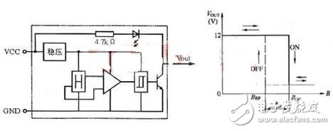
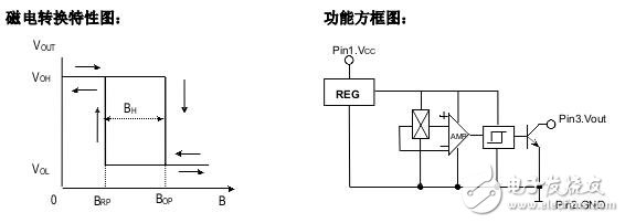
Under the action of the external magnetic field, when the magnetic induction strength exceeds the threshold bop, the hole circuit output tube is conduited and the output is low. Then b increases, and the circuits remain conductive. If the b value of the magnetic field is lowered to brp, the output tube is closed and the output level is high. We call bop the work point, brp the release point, bop-brp = bh the return difference. The presence of reversibility increases the resilience of the switch circuits。
620)this. Width=620; "syle=cursor:point"/
Iii. Hall switch - rationale structure
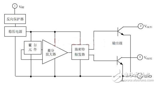
The hal switch circuit consists of seven components: a reverse voltage protection, a precision voltage regulator, a hall voltage generator, a differential amplifier, a schmidt trigger, a temperature compensater and a complementary integrated pole opener. A brief description of the functions of each section follows。
Pressure adjuster: when power voltage changes from 3. 5 v ~ 20 v, the circuit is guaranteed to work。
(a) reverse protections: protection of circuits to the extent of 30 v when the power is being used in reverse or when it is disturbed by reverse pulse voltage during use;
Hall voltage generator: converts the altered magnetic signal into the corresponding telecommunications number。
Discrepast amplifiers: magnify the weak voltage signal from the hole voltage generator。
Schmidt trigger: converts analogue signals from differential amplifiers to digital signals。
Temperature compensator: ensure reliable operation of integrated circuits between 20°c ~ + 85°c。
Complementarity output: the output current can directly drive two groups of unbrushers。
620)this. Width=620; "syle=cursor:point"/
As can be seen from the above figure, when the power is connected without a brusher, if the hole voltage generator is activated by a transmagnetic field, the level of the output end 2 and 3 is changed, thereby changing the direction of the load current and making the winder operational。
Hall switches - classification
1. Monopolar holhol effect switches (digital output)
The unipolar hormone switch has a magnetic working threshold (bop). The output transistor will be activated if the magnetic flux density of the hole module is greater than the working threshold; the transistor will be closed when the magnetic flux density is below the working threshold (brp). The lag (bhys) is the difference between the two thresholds (bop-brp). Even with external mechanical vibrations and electrical noises, the built-in lag page achieves a net rotation of output. The digital output of the unipolar hole effect can be adapted to various logical systems. These devices are well suited for use with simple magnets or magnets. The unipolar horde switch will have a magnetic polar sensor on each side of its back, and attention should be given to the installation of magnets in the specific application, which in turn will cause unipolar insulation。
2. Bipolar holhol effect switches (digital output)
The bipolar hall, in particular, divides bipolar and unlocked hall switches and bipolar lock hal switches。
The bipolar hormone effect switch is usually opened with sufficient strength in the antarctic magnetic field and closed with sufficient strength in the arctic magnetic field, but if the magnetic field is removed, it is randomly exported, possibly open or closed. The binocular lock-in hol effect switch is usually opened when the strength of the antarctic magnetic field is sufficient and closed when the arctic magnetic field is sufficient, but if the magnetic field is removed, the output status will not change. These halo effect switches can be magnetically driven using a north-south transversal magnetic field, a multipolar ring magnet。
3. Two-polar lock-in halo effect switch (digital output)
When opened at the n (or s) pole, the magnetic field continues to be opened when removed; and only when closed at the s (or n) pole, the magnetic field remains on or off when removed until the next magnetic field changes. This feature, which maintains the previous state, is the locking feature, and this type of hall benefits switch is the binary lock-in-the-hall effect switch。
4. All-horon effect switches (digital output)
Unlike other hormone-effect switches, they can be opened as long as there is a sufficiently strong arctic or antarctic magnetic field; when there is no magnetic field, the output is closed。
5, linear hole effect sensor ic (simulation output)
The voltage output of the linear hole effect sensor ic accurately tracks changes in magnetic flux density. In static (no magnetic field), the output should theoretically equal half of the power voltage within the working voltage and working temperature. An increase in the antarctic magnetic field would increase the voltage from its static voltage. Instead, an increase in the arctic magnetic field would increase the voltage from its static voltage. These components measure the angle, proximity, motion and magnetic flux of the current. They can reflect mechanical events in a magnetically driven manner。
6. Micro-utilization hall effect switch (digital output)
With the widespread availability of portable devices such as mobile phones, laptops and dvs, demands were made on holic, resulting in a large new category of holic. It is a separate category of the number holic, which uses a hibernation mechanism to reduce the amount of effort, with average usage reaching the ua level. It can also be divided into functionally single-level holloic, lock-in, and full-scale holloic. Such systems are generally used for battery long-term power。
V. Hall switches - validation
A simple way for you to do this: hall looks to himself (stamp) with the tube foot down, from the left to the right: positive poles (horrow 4. 5 to 24v, linear hole 5v), negative poles, loss (sign) and electrical resistance (1 to 10k) at the positive pole and output. In negative poles and output, an indirect light-emitting diode (or the measurement of voltage by a universal meter, high power is equal to the low voltage level of about zero). Electronization can be followed by a magnet approaching or away from hall to see whether the luminous diode is luminous. It's good if it changes, it's bad if it doesn't。
Vi. Hall switch - monode switches (oh137)
Hall switches are divided into unipolar switches and binary switches, with oc137 below being a unipolar switch, which can be consulted online for oc413, oh41, etc., for reference computers, as shown below。
Oh137 hall switch circuits are designed to apply low-cost, high-performance requirements of customers to develop a catalogue of products that are widely used and have reliable and stable performance. The internal circuit consists of reverse voltage protections, voltage adjusters, hall voltage generators, differential amplifiers, smitt triggers and holocaust open circuit outputs, which translates the altered magnetic field signals into digital voltage output。
Typical areas of application: straight currents without scrubbers, household appliances, sewing equipment, textile machinery, encoders, security alarm devices, etc。
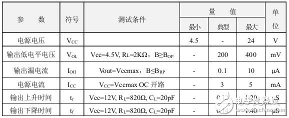
Limit parameters: (ta = 25°c)
Power voltage vcc. . . . . . . . . . . . . . . . . . . . . . . . . . . . . . . . . . . . . . . . . . . . . . . . . . . . . . . . . . . . . . . . . . . . . . . . . . . . . . . . . . . . . . . . . . . . . . . . . . . . . . . . . . . . . . . . . . . . . . . . . . . . .
Output load current io, .. . . . . . . . . . . . . . . . . . 25 ma
Working temperature ranges ta
Storage temperature ranges ts .. . . . . . . . . . . . . . . . . . . . . . . - 55 ~ 150 °c
620)this. Width=620; "syle=cursor:point"/
620)this. Width=620; "syle=cursor:point"/
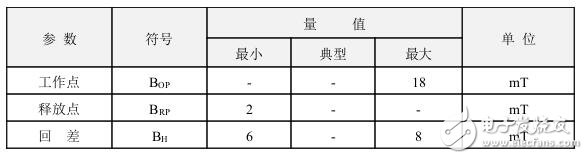
Magnetic properties: (vcc = 4. 5-24v) 1 mt = 10gs
620)this. Width=620; "syle=cursor:point"/
Test the circuits
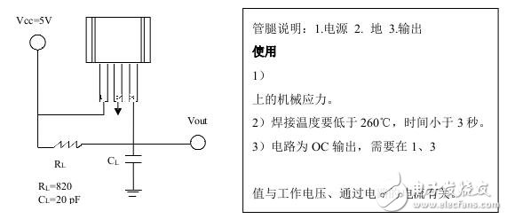
620)this. Width=620; "syle=cursor:point"/
Appearance size diagram:
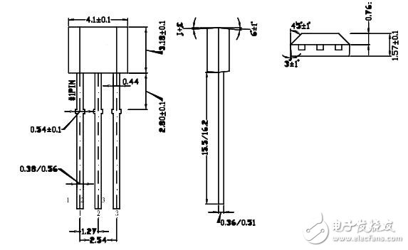
620)this. Width=620; "syle=cursor:point"/
Vii. Hall switches - application of integrated sensors
The basic uses of hall switch integration sensors include the following areas: ignition systems, security systems, speed conversion, routing, mechanical equipment limit switches, button switches, electrical current determination and control, location and angle detection, etc。
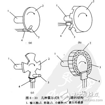
(1) hole speed sensor. Figure 8-30 shows the structure of several halo-referral sensors。
620)this. Width=620; "syle=cursor:point"/
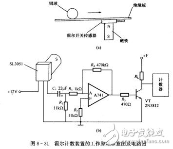
(2) hall counting device. Figure 8-31 illustrates the working principles and circuits of the hole sensor's device for steel ball count。
620)this. Width=620; "syle=cursor:point"/
Because the steel ball is a powerful magnetic object, the stationing of the hydro-dry magnet in the device as having a steel ball rolls out, and a change in the magnetic field, as well as a change in the voltage of the sensor's output, is tantamount to a pulse, which is amplified by an operation amplifier. The tripod of the triode is operated once, and a counter is attached to the condensation pole of the triode, which counts the rolling steel ball。
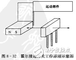
(3) hall approaches switches (figures 8-32). The motor parts are equipped with a permanent magnet and their axes are on the same line as the sensor. When magnets move from several millimetres to ten millimetres (described by design) with the motion component, the output of the sensor changes from high-to-low to low-to-power level, driven circuits absorb or release relays, and the motion component ceases。
620)this. Width=620; "syle=cursor:point"/