Introduction
Power conversion systems in microreversers are usually designed in two-stage format, as shown in figure 1-1。
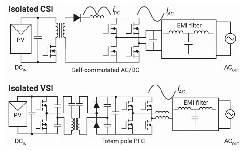
Figure 1-1 microreverse two-stage expansion
In such a scheme, the direct currents provided by the photovoltaic panels are converted to a temporary straight-flow bus, usually around 400 vdc. The current bus is then converted to communication voltage (110 vac. 230 vac) depending on the national or regional grid. The power level used to be between 300-400 w, but implementation of each input power up to 600 w and multiple input systems has recently emerged. Microrevers have traditionally been constructed as one-way converters, as electricity flows from pv panels to communication grids. There are two main types of implementation: isolated current retrovertors (csi) and isolated power retrovertors (vsi). Vsi is slightly more complex, but more efficient when it has a comparable level of power. Optical panels need to be isolated from high pressure communication by means of a separation fence to avoid electrical hazards when people touch the panels. In addition, the level of isolation can reduce leakage from commodular voltage in parasitic capacitors。
To use an isolated straight-flow/ straight-stream two-way system for energy storage systems, changes are required to replace a push-over or inverse stage with a two-way converter such as a cllc or a double powered bridge (dab), as shown in figure 1-2. The communication/direct flow level remains the same, either as a totem pole pfc/reverser or as a unipolar or bipolar fully operated bridge. For differences in communication/direct flow, see tida-010938 (configurable communication/direct flow) design guide。
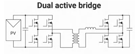
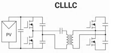
Figure 1-2 two-way power level expansion for portable power stations
Reference design tida-010054 describes the working principles of the two powered bridges, while reference design tida-010933 describes the working principles of llc or cllc converters. Clllc is a booster that controls the mmu to control output power using frequency modems. The resonance controller is highly efficient when operating within a narrow range close to the frequency of the resonance. Two powered bridges usually operate at fixed frequencies, with power streams being controlled by the movement between the input and the output bridges on both sides. Both options have advantages and disadvantages. The choice of which option depends on the system requirements, such as input and output voltage ranges。
The power efficiency of the two-stage converter is usually limited to 96 per cent (from direct flow to communication), especially when using a single-direction two-brasket operation in the whole stream. From the point of view of the number of pure power switches, it is easy for two-stage converters to have up to 10-12 high pressure switches。
This paper presents a new single-stage converter reference design, tida-010954, which makes the implementation of the above-mentioned terminal equipment more efficient, smaller in size and lower in cost. The power conversion control algorithm is based on an extension shift, which reduces the requirement for mmu speed and software complexity。
2. Circulation converter basics
Cyclical converters or recyclable reversers convert one constant range and frequency exchange waveform to another lower frequency waveform by synthesizing the output shape of the parts of the exchange source that have no middle direct flow links. For the example of a microreverse or portable power station, the waveform is entered as a pure straight current. Output is a network connection. Figure 2-1 illustrates intuitively possible implementation options。
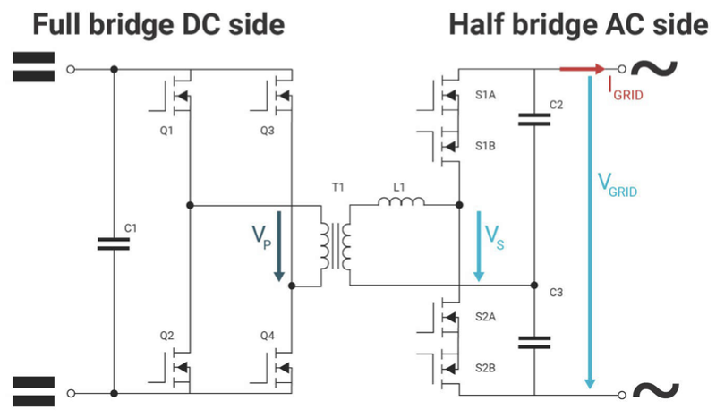
Figure 2-1 cycle converter for the whole bridge on the straight-stream side and the semi-bridge on the communication side
In this case, the whole bridge is implemented on the straight-stream side to generate input signals on the primary side of transformer t1. Implementation of semi-bridge configuration on the side of communication (with a capacitor subpressor) to simulate vgrid exchange output of vs segments on the side。
For positive output signals, switches s1b and s2b are permanently enabled. The converter can be regarded as a two-power bridge operating in a sequential manner. Pwm imposed on s1a and complementarity applied to s2a, while the output voltage and current were similar. The power size of the transfer is determined by the shift between vp and vs. For negative output voltage, s1a and s2a permanently channel. Similarly, switches s1b and s2b form a double powered bridge for negative output voltage and current。
In the reference design tida-010954, the ti gan device is used to run the converter at a fast switch frequency in order to minimize the volume of all magnetic elements without sacrificing efficiency。
Why use gan?
Cyclical converters are a soft switch extension, which means switch losses are negligible。
Gan fet has a much lower rate of breakage compared to sic or sifet。
The output capacitor of the gan device coss is lower than sifet. This contributes to a wider range of zero voltage switches。
The rdson of the drive-through-depletion device determines how much the converter will eventually lose。
The equipment used on the primary side is 100v gan half bridge lmg 2100r026 (rdson is 2. 6m). For the secondary side, a 650v gan device with an integrated grid polar drive: lmg3650r035 (rdson 35m)。
3. Design precautions and effects
As long as the switch is operated in soft switch mode, it is more efficient to move two power bridge converters. This is difficult to achieve when the secondary side voltage changes (e. G., the chord wave on the side of communication). Two sequential controls were implemented in tida-010954. Control methods are described in the following ieee paper. For high power, mode ii is implemented near the communication peak. For small power (over zeros of communication slopes and communication signals), mode iii is used. The transition control differences for modes ii and iii are shown in figure 3-1。
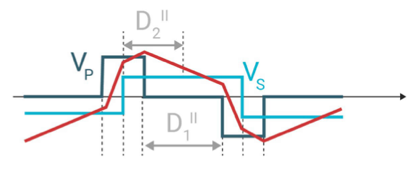
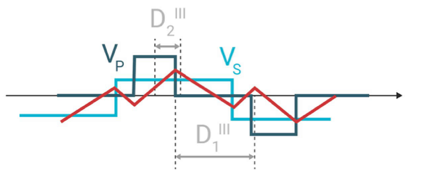
Figure 3-1 diversion mode and control variable
Control variables d1 and d2 are used to control power currents and are calculated in the microcontroler (tms 320f28p 550) according to the mode of operation of the converter. It should be noted that under mode ii, primary voltage vp always leads to secondary voltage vs to achieve positive power transmission. Vp always lags behind vs for reverse power transfer. This is to enable the converter to perform high power transmission in soft switch mode. Under mode iii, primary voltage pulse vp is fully contained in secondary voltage pulse vs. This is to reduce rms currents in transformers and to reduce passivation losses in switches. In addition to phase control, frequency controls are implemented to maintain smaller rms currents in transformers while the converter light loads. The working frequency of the converter varies between 300 khz and 600 khz。
The extension phase transfer with variable frequency modems is controlled at the kernel of tms320f28p550 (clock speed 150mhz) with 20khz (50us) running in the service interruption routine, requiring less than 40% mmu utilization. This adds an additional supporting organizing routine and runs controls on a single mmu. This low utilization rate has been achieved because microcontrollers have advanced features such as "configurable logic block (clb)" to run time-critical codes in hardware without having to load mmus. In addition, tms320p550 has an excellent external set-up that allows for the simultaneous updating of pwm in a very short period of time for phase transfer and frequency modems. In order to achieve this function on traditional mmus, additional fpga or asic implementation is usually required to implement these combination control algorithms。
Simulates the design using the plexim emulator to predict the normal functioning of control before the hardware is built。
Figure 3-2 shows the simulation results of 40vdc input and 230vac output under two different load conditions (300w and 600w)。
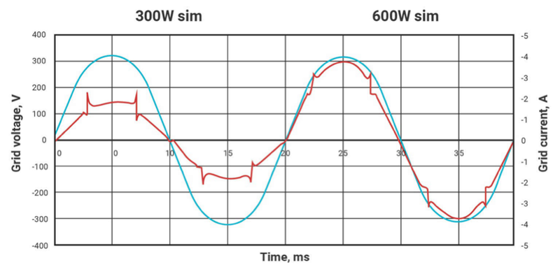
Figure 3-2 300w and 600w load conditions
Modular changes can be observed during simulations, i. E. Small peaks (reds) in current wave shapes when converters change working patterns。
Tida-010954 uses standard 6 floor pcb manufacture. All gan devices are cooled at the bottom, with power being dispersed to pcb without additional heaters. Figure 3-3 shows the image of the converter. The power density of the design is approximately 600 w/l. This is about twice as high as the current commercial two-stage microreversers with the same rated power。
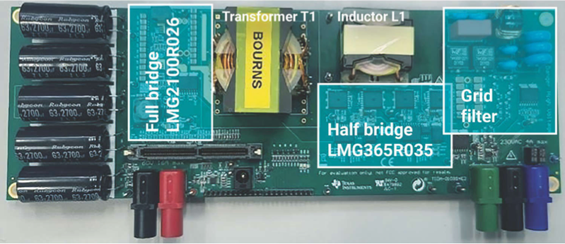
Figure 3-3 photos of the circular converter tida-010954
The converter was measured under various load conditions in the laboratory. Figure 3-4 shows the time-area measurements of the converter exchange output。
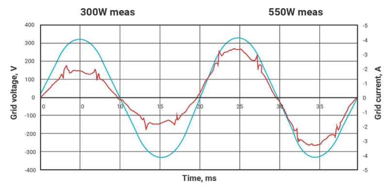
Figure 3-4 300w and 600w load conditions measured
The perfect match between simulations and measurements is shown in figure 3-2. The total harmonic distortion measured at 600w under full load conditions is only 2. 6 per cent, far below the 3 per cent requirement for grid-connected microreversers。
Testing under different load conditions is an important performance parameter. The converter needs to be efficient not only under full load and 50% load, but also under light load conditions. Figure 3-5 gives the measured efficiency curve. The peak efficiency is about 97 per cent。
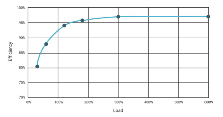
Figure 3-5 measuring the relationship between efficiency and load conditions
We defined weighted efficiency to compare microreverse designs. The most common definitions are euro and cec efficiency. The above curve represents approximately 95. 4 per cent for euro and 96. 4 per cent for cec. This efficiency is high compared to market-based solutions based on traditional two-tier solutions。
4. Cost optimization
System costs are an important consideration in the design of micro-reversers or portable power stations. This section explores in depth how the migration from the sifet-based two-stage converter to the gan-based single-stage converter has a positive impact on system costs. In circular converters, the number of power switches can be reduced. For push-and-retort converters, a switch rated voltage of 170 v is required on the straight-flow side; for cycle converters, a single panel entered a rated voltage of 100 v. The working frequency range of this new cycle converter ranges from 300 khz to 600 khz. This means that magnetic component designs (reverters and sensors) are much smaller than two-stage converters. The working frequency of the two-stage converter is usually less than 100 khz to keep the sifet switch less depleted. In addition, the emi filter required for a cycle converter to access the grid is much smaller than the full bridge exchange/direct flow converter. This reduces overall costs. Figure 4-1 shows cost comparisons. The cost of the shifter is used as a 100% benchmark for relative comparison。
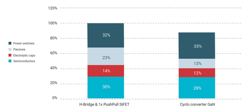
Figure 4-1 cost comparison
The cost of power switches increased slightly, while the cost of magnetic components decreased significantly. As a result, the cost of the overall solution was reduced by 12 per cent。
5. Concluding remarks
This technical white paper outlines a new type of single-stage converter (cycle converter), which makes the implementation of microreversers and portable power stations more efficient and smaller in size, while reducing costs. Power conversion control algorithms are based on extensions with additional frequency modems. This increases the efficiency of the lower and middle output power levels. By using a new real-time c2000tm mmu, control algorithms can be run without external fpga or dedicated asic。