* reissued for technical reasons
The core of the two standard electromagnetic valves will move at high speed and completely to a new position (thus known as the switch-off of the electromagnetic valve). This rapid movement of the entire process will result in the implementer beating or rushing on start-up and excessive impact upon cessation. Pressure peaks and shocks generate noise, can damage machines and adversely affect pipelines, leading to leakage。
Soft switching of electromagnetic valves with hydraulic pressure inhibiting the movement of the core of the nitric valve can slow the switch and reduce the impact in some applications. However, many machines require variable switching speeds to adapt to changing power and work requirements. The soft switch electromagnetic valves with variable flow control provide a wider range of regulation and better control of certain oil routes。
Other options include valves with specially designed flow control devices and valve core processors, which can be configured according to the functions of a particular machine. This type of variable valve can work on some machines, but requires many precise adjustments to achieve the required implementer control。
The variable charge two-way pump in the closed loop circuit provides a very smooth movement, but is limited to operating a single implementer. For extremely precise controls, a server valve with an implementer feedback is the final motor controller. The ratio valve is between the service loop and the other above-mentioned controls。
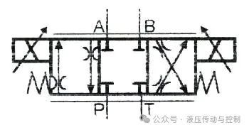
Figure 14-1. Direct motion scale valves
How does the scale valve work
The scale valves are well suited to the circuits that need to reduce shocks and vibrations by altering flows or pressures. Electromagnetics on these valves move more or less more of the cores according to the voltage that is applied to the proportional magnet. They can change the speed at which the core moves or the distance at which the core moves. Since the cores in the scale valves do not move completely at once, they control the acceleration and deceleration of the implementer。
Usually, speed acceleration and reduction is controlled by changing the time at which the valve core is cut. The maximum speed of the implementer is controlled by limiting the flow of the core by altering the voltage of the ring. Computers, personal computers, programmable logic controllers (plcs) and even simple transformers can produce variable telecommunications numbers。
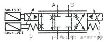
Figure 14-2. Simplified symbols for the electromagnetic pilot scale valve with lvdt
If the flow is low (less than 20-25 gallons per minute), a direct electromagnetic-driven ratio valve can be used, as shown in figure 14-1. Directly driven valves are smaller and less expensive than electromagnetic precursor valves. However, the electromagnetic pilot ratio valves can handle higher flows — some can even exceed 200 gallons per minute。
Figure 14-2 shows the simplified symbol for the electromagnetic pilot scale valve。
Figure 14-3 shows the full symbol of the same valve. The complete symbol includes the details of the lead control valve and the main valve, the pressure relief valve in the lead circuit and the direction of the lead pipe。
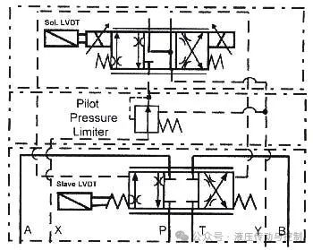
Figure 14-3. Complete symbol for the electromagnetic pilot scale valve with lvdt
Simple scale valves rely on the balance of electromagnetic and spring forces to locate the core of the valve. Due to changing flow, pressure, temperature and fluid cleaning, the given input voltage may not always produce the same core position. In order to improve the accuracy of the core position of the valve, linear variability transformers (lvdts) can be used, as shown in figures 14-2 to 14-5。
The linear variable-variable transformer (lvdt) will electronically compare the input signal to the core position of the valve and adjust the voltage so that the same core position can be maintained regardless of changes in the system. While lvdt increases the cost of valves and electronic devices, it is usually necessary for all applications except simple acceleration/reducing circuits。
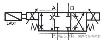
Figure 14-4. Direct lvdt scale valves
Lvdt cannot control the repetition of traffic through the valve because the flow is a function of pressure variance, fluid viscosity and the size of the hole. Changes in pressure or fluid viscosity change the speed of the implementer. In order to reduce the change in speed, feedback signals from the implementer can be increased (like the server valve circuit). The implementer feedback will help, but it is still not accurate because most ratio control valves are not responding fast enough to overcome sudden changes in the system。
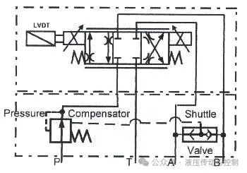
Figure 14-5. Directly motionable scale valves with lvdt and pressure repairers
In figures 14-5, pressure compensation valves in pipelines reduce flow volatility due to changes in system pressure. Pressure-compensators maintain constant pressure differentials at both ends of the valve core vent in order to maintain constant flow in the event of a change in the oil flow or work pressure. Pressure repairers are pressure relief valves with fixed spring values (e. G. 150 psi). A shuttle valve provides pressure feedback from each tank port to the remote control of the pressure reduction valve. When the pressure in the working port changes, it changes the pressure of the pressure reduction valve to maintain a constant 150 psi pressure difference at both ends of the proportional valve core。
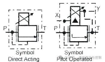
Figure 14-6. Proportional spillovers valve
The right circuit design determines the control of the scale valve
Transmit a telecommunications number to a proportional electromagnet to alter the force of the valve or hole, thereby achieving unlimited variability control over pressure. Figures 14-6 and 14-7 show the symbols of the impenetrable spill valves and the pressure reduction valves. The pc or programmable logic controller (plc) can be used to generate variable signals to change pressure at any time when the machine runs the sequence required。
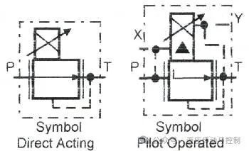
Figure 14-7. Proportional reduction valve
The use of proportional pressure valves for remote control of pressure compensation pumps also makes them more generic。
Figure 14-8 shows the symbol of a screwdriver valve. When the flow exceeds 150 to 200 gallons/minutes, the spill valve may be plugged in with a direct-action ratio spill lead valve. These plug-in valves have separate valves and are part of special large flow valves。
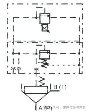
Figs 14-8. Sliding covers insert spill valves - ratio control to achieve limitless variability of pressure
Proportional control valves are more tolerant of pollution and less costly than the server valves they often replace. When circuits do not require very high precision or traffic repetition, savings in initial costs and lower requirements for filters make the scale valve a good choice。
One reason why the server system is more accurate is the electronic feedback from the implementer. The feedback signal adjusts the core position of the server valve so that the implementer is in a precise position or produces the exact speed or force required by the controller. The scale valves may also have feedback controls, but their response times are too slow to achieve the precise controls provided by the server valve circuit。
Figure 14-9 shows a ratio valve for current-saving functions. This is an inflexible, electro-controlled current valve. As the voltage of the ring increases, the core moves further, increasing the flow. The symbols in figures 14-9 show that the valve is connected to a single flow path。
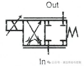
Figure 14-9. Directly driven lvdt-free throttles
The two-way path shown in figures 14-10 provides twice the flow at the same pressure differential in either flux path. The throttles shown in figures 14-10 can be used to control traffic in bypass or bypass circuits, or to control flows to or from traditional electromagnetic valves。
The throttle function can alter the flow to an implementer that requires frequent or continuous adjustments. The throttle valves can also be used alongside the traditional direction valves in order to achieve a smooth acceleration and deceleration of the hydraulic tank, thereby eliminating the impact。
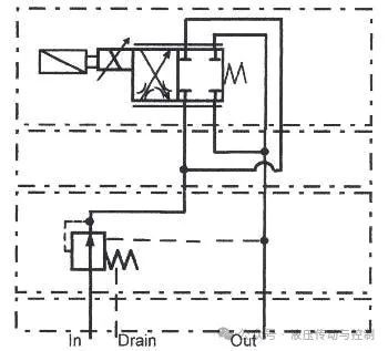
Figure 14-10. Direct electromagnetic-drive throttle valves with lvdt feedback, combined flow path modules and pressure-compensation swing modules
The speed of the implementer can be controlled by the installation of throttle valves in the return pipelines of traditional electromagnetic valves. When the throttle is installed at this location, the implementer will not lose control. It is important to ensure that the direction valves are capable of absorbing any back pressure generated by a circuit that is greater than that generated by the circuit。
The installation of a throttle in the main pump line can alter the speed of an implementer or units (they circulate at different times). This type of circuit is less costly but requires more complex electrical control circuits。
The throttle configuration shown in figures 14-10 can achieve non-variable flows. A hydraulic pressure stabilization module is added to the pump pipe to maintain constant pressure differentials at both ends of the hole. The flow will not fluctuate due to constant pressure. Since the four valves do not have a reverse flow, both flow paths can provide fuel for the circuit. The pressure differential of any flow path is nominal in the specified flow. This configuration achieves double the nominal flow without creating additional pressure differentials or heat。
All traffic paths of the combined flow path module have been drilled internally and resized to minimize the pressure differential. The module is optional in sizes d03 and d05, with traffic of approximately 50 gallons per minute。
The use of proportional control valves reduces impact and provides more sophisticated control over circuits that do not require high position precision or repeatable speed and power。
The scale valve limits the flow to and from the implementer. They are best used in closed loops with pressure-compensation pumps. The addition of energy collectors on circuits increases the cycle response time and protects pumps from pressure peaks. A system using a scale valve usually requires a cooler because the energy of such circuits is more wasted。
The following section describes some circuits - and provides some points for the use of scale valves in several applications. Always keep in mind that the size of the scale valve is selected on the basis of maximum flow and pressure differentials to obtain the best response and repetition of the circuit。
Backway design for scale throttles
The circuits in figures 14-11 and 14-12 control the acceleration and deceleration of the implementers. Sending electronic signals to these circuits can also change the speed of the transmitter indefinitely。
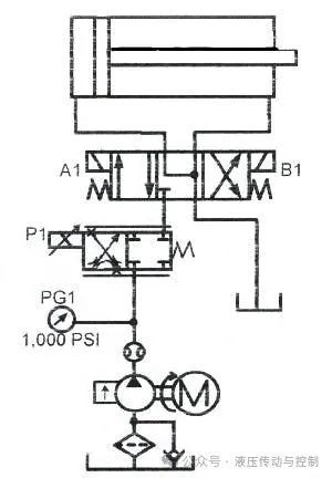
Figure 14-11. Proportional throttle in fuel-saving circuits of pumping pipelines for flat acceleration, deceleration and speed control
In figures 14-11, the proportional throttle in the pumping pipeline controls the flow to traditional electromagnetic valves. This circuit only applies to resistance loads because it controls the flow of hydraulic cylinders. In order to reduce energy waste, load sensor pumps can be used and the piping between the ratio valve and the direction valve can be detected. Load sensing allows the system to operate under lower pressure during most cycles. Load sensing also provides pressure compensation for circuits。
The proportional throttle in figures 14-12 controls the pipelines of the traditional electromagnetic valves. This circuit is applied to the overload because it controls the fluid from the hydraulic cylinder。
Note: the direction valve may be subject to pressure up to twice the defined value of the pump. Please ensure that the pressure does not exceed its rating value for the circuit. In such throttle export circuits, harmful shocks may occur if the throttle is suddenly switched. In this application, proportional amplifiers with adjustable slope functions should be used。
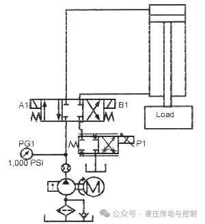
Figure 14-12. Proportional throttle in the run-back export route to the pipeline route - used to achieve smooth acceleration, deceleration and speed control
If hydraulic cylinders need to be set without a crawling line, a balancing valve should be used. The internal leakage of the throttle may not prevent the drift of the hydraulic tank. In such circuits, the balancing valves must have external oil spills. The pressure on the back of the balance valve at the export will alter the pressure set for the internal discharge valve。
Traditional valve loops for resistance load applications
Horizontally installed hydraulic cylinders usually require strength throughout the journey. This hydraulic tank configuration is called resistance load application. Heavy loads usually require accelerator and deceleration during high-speed operations to achieve smooth operation. One way to control acceleration in these circuits is to switch the traditional open circuit back-magnetic valve to reach out to the hydraulic tank and, during the acceleration process, to allow excess pump flow back to the tank through the spill valve. In this part of the cycle, there are smaller pressure peaks and some heat, but otherwise the discharge of the hydraulic tank is stable。
The rationale chart in figures 14-13 shows a double pump in a high-pressure circuit, operating in this way. Figure 14-14 shows a closed loop valve and pressure reimbursement pump. This configuration eliminates part of the pressure peak and reduces heat generation, but at higher cost。
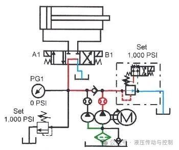
Figure 14-13. Typical high-pressure pump loops with smooth acceleration and slower implementation device
When the hydraulic cylinder approaches the end of the process, a limit switch removes the load of the high-pressure backway high-flow pump, which slows at the speed permitted by friction of the machine component. When the hydraulic tank is reduced to the speed of the small flow pump, it continues to reach the end of the journey at a sufficiently low rate to eliminate most shocks. (in this application, hydraulic cylinders with standard buffers can eliminate almost all shocks
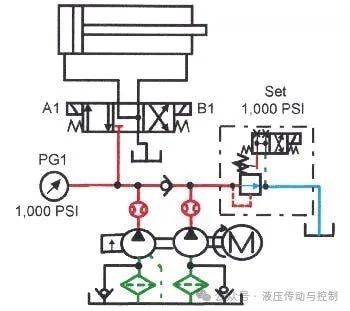
Figure 14-14. Pressure-compensators and quantitative pump loops, smooth acceleration and deceleration device
Figure 14-15 shows a shock-free circuit. Here, a pressure-compensatory by-flow valve discharges excess traffic from a single quantitative or pressure-compensation pump. The speed of slowdown still depends on the friction of the machine. Secondary velocity can be adjusted as needed。
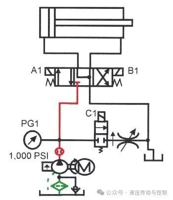
Figure 14-15. Pressure-compensation pumps and throttle loops that can steadily accelerate and slow implementation device
Another method of slowing loads is to order hydraulic cylinders with buffers that are longer than standard buffers and have a gradual flow cut-off. When ordering a gradient buffer, load, pressure and velocity shall be specified. Gradient buffers are very effective for machines with fixed working parameters. If the load changes, the gradient buffer is effective only in a narrow part of the range。
Application of ratio valves in resistance load loops
Figure 14-16 provides a scale valve and a pressure reimbursement pump to cover all the situations mentioned in the previous section. Through such circuits, acceleration and deceleration can be fully reconciled within a wide range. When load, velocity or pressure changes, control parameters can easily be changed to adapt to new circumstances. Usually, the electro-detachor adjusts the switch speed of the valve core between zero and five seconds. In order to compensate for changes in fluid viscosity, pressure or load, the speed is reduced to a minimum climb speed through a limit switch at the end of the process and the valve is finally completely closed。
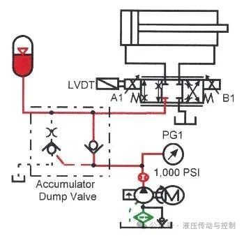
Figure 14-16. Pressure-compensation pumps and proportional valve circuits that can steadily accelerate and slow down implementation device
Proportional valve for uncontrolled load
The vertically installed portable cylinders are usually out of control in one direction or exceed the pump flow. When a switch direction valve is switched, the hydraulic tank falls free. Freefall is a security hazard that may cause damage to tools or machines。
The balance valve in figures 14-17 controls uncontrolled hydraulic cylinders. The valve allows the flow of flow from a hydraulic tank at the uncontrollable end at the same speed as the pump to the other end. When the hydraulic tank travels in the opposite direction, the load is of a resistance type. When using the balance valves, acceleration and deceleration can be controlled by any resistance load loop mentioned in the previous section。
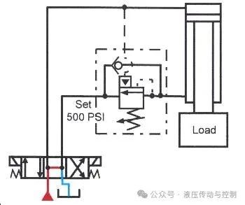
Figure 14-17. Typical balance valve circuits with internal and external lead for control of uncontrolled loads
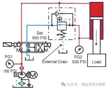
Figure 14-18. Control of uncontrolled hydraulic cylinders when outstretched by proportional valves and balance valves for external spills
The proportional direction valve controls the flow to and from the implementer, so that there is pressure at both ends when the implementer moves. When used with the proportional direction valves, the balancing valves usually require external discharges. In the absence of external discharges, pressure at the export side of the balancing valve increases spring setting, thereby preventing the valve from opening. Please note that the circuits in figures 14-18 show external spill lines on the balance valve. In such circuits, when the proportional direction valves are rapidly centered (e. G., when the emergency stops), the hydraulic cylinders will cease flat。
Proportional direction valves control uncontrolled loads, as most core designs control flow to and from the implementer. If the implementer is a hydraulic motor or a double-barrel hydraulic tank, the volume of import and export is the same. When the proportional valve is switched to the mobile implementer, the restricted flow from the other side controls acceleration, deceleration and maximum speed。
However, most hydraulic cylinders are monopolized, which means that the volume from the end of the pole is smaller than the volume from which the end of the pole is reached. The volume difference is close to 50 per cent when 2:1 hydraulic cylinders are used. In this hydraulic tank, the size of the pole is equal to half the area of the piston. (some manufacturers provide ratio valves with valve cores, which allow only about half the flow through the end of the pole. These valves fit well with two: one hydraulic tank
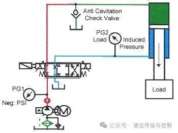
Figure 14-19. Control of uncontrollable hydraulic cylinders with a one-way gas-resistant valve
There may be two problems with the use of standard valve core scale valves and single rod end hydraulic cylinders and uncontrolled loads. Figure 14-19 shows that the hydraulic cylinders were out of control from the pumps, resulting in air erosion without poles. Hydraulic cylinders are out of control because the flow-exit function of the proportional direction valves discharges more oil than allows access to unadvised oil. Since no pole can be kept full, loads are suspended until the pump fills with no pole. When the hydraulic tank runs in front of the pump, a one-way gas protection valve is used to allow fluids from the tank to enter the endless end of the hydraulic tank. This circuit applies to the use of uncontrolled loads at the end of a hydraulic cylinder pole。
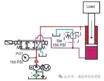
Figure 14-20. Ratio valves with external lead pressure control control control control of hydraulic cylinders that are out of control when they reach out

|/