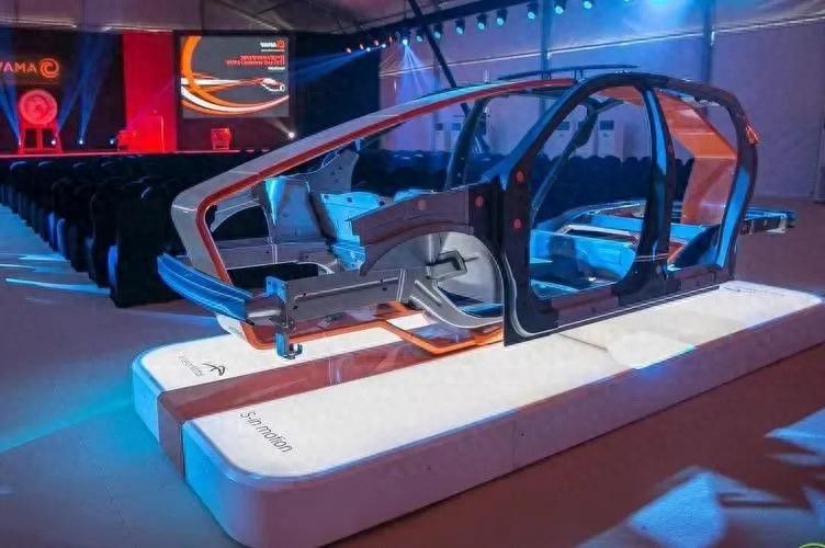
As cars move, they often need to change their course, and when they move along straight lines, the wheel is often subject to side-to-side interference and automatically deflects direction, when drivers need to use a set of institutions to shift the wheel in the opposite direction, thereby restoring the car to its original direction, a set of specialized agencies used to change or restore the direction of the vehicle, known as the shift system。
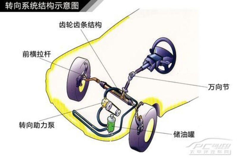
The function of switching to the system is to ensure that the car changes course according to the driver's needs, and that it also overcomes the side-to-side interference and turns the wheel itself, and restores the car to its original direction. The tectonic transformer is a gear-down and force-enhancement device in the system, which is used to increase the power of the steering wheel to the twilight and to change the direction of the force. A wide range of gear-coated and circular switchers is currently being applied. Gear bar turnsers: the gear bar turnsers consist of small gears, turn gears, turn poles, etc. Small gears are installed on the shell and are combined with rotor rodents installed horizontally within the shell. Transverse poles are installed at both ends of the gear. When the steering wheel turns, the small gear turns and drives the condensed turn of the gear along the axis, leading to the right and the left to the pull pole to the right and the left to the right and to the left, to the wheel to the other and to the car to the other。
Gear gears turners: the rollers consist of steering axes with snails, steel balls, guide tracks, ball screws, fan axes, etc. When the steering axis with a snail turns down the steering wheel and the steering column, the steel ball transmits the force to the ball nut, which moves along the axis. At the same time, under the friction of both the snail and the snail and the steel ball, all the steel balls roll in the threaded pipe to form a current. Turn to the nut-enabled fan axis, which is re-enabled to pull the pole and turn the wheel。
The shift from a circular to a manipulator structure to a manipulator structure consists of a steering wheel and a shift column, among other things, the function of which is to transfer the driver's manipulation of the steering wheel to a switcher. The types of transition to the transmission structure and the composition and placement of the moving body vary. The diversionary structures that are compatible with the non-independent hangers are shown in the figure below. The shifting apparatus that is compatible with the stand-alone hanger is shown in the figure below. Hydraulic-to-system tectonic-dynamic shifts are those in which only a small proportion of the power source comes from the driver and the rest is provided by hydraulic systems or electric motors. Hydraulic gear gear gear power switching systems consist of power-to-pumps, liquid storage tanks, hydraulic piping circuits, gear-bar transferers, etc., as shown below。
Hydraulic gear gear gear power shift system 1. Hydraulic power shift to work principle power shift system uses engine power to drive a leaf and wheel pump generating liquid pressure. When the wheel turns, converts the oil route on the control valve. When the oil pressure is applied to the power pistons in the power tank, the power required to manipulate the wheel is reduced, as shown in the figure below. 2. Hydraulic-to-pump power is the power source of the hydraulic-powered system, which functions to transform the mechanical power of the engine into the hydraulic energy that drives the work of the motor-cylinder and to transfer to the power-cylinder. Hydraulic steering pumps are usually installed at the front end of the engine. Hydraulic power turns to pumps in rolling columns, blades, rotors and gears. Leather-type hydraulic power shifts to pumps are simple, reliable and widely applied, as shown in the figure below. Electro-assisted tectonic principle electronic-aided system (electro)Nic power moving system, eps (see figure below) is a system of electric power conversion that relies directly on electric motors to provide back-to-back. The system uses micro-machines to control the direction and range of electrically driven currents, does not require complex control structures, and electric motors, speed-reducing structures, shifts to columns and gears can be integrated。
? The electronic control enabler turns to system 1. The transformer structure has two small gears and electronic control enablers to shift to the system, as shown in the figure below. The two smaller gears are arranged in parallel, and are combined with the rodents. The first small gear is driven by the steering wheel through the shift column and the moving device. The shift from power to power is driven by a second small gear through a moving agency as a system enabler。
The electronic control enablers with two small gears to switch to the system transformer structure 2. The electronic control shift to the system principle is shown in the figure below。
The function of the transition process is 1 - to rotate the wheel, to shift the force; 2 - to detect the twisting of the wheel and transmit the detected twist to the electronic control unit; 3 - to transfer the current angle and speed to the electronic control unit; 4 - to calculate the signal of the shift, to turn the engine, to turn the angle, to turn the speed sensor, to support the twist and to activate the auxiliary electric motor; 5 - to transfer the support power through the wheel transfer device and the second small gear to the gear of the gear; 6 - to shift the wheeling and the support twisting combination of the boosting motor is an effective twist on the wheel, which causes the gear to be moved
Active re-entry of wheel 1 - when moving in a curve, the driver lowers the turner to the twister and the twister sensor informs the electronic control unit; 2 - electronic control unit calculates the recoiling rectangles based on the turner, shift angle and speed; 3 - shift to the wheel does not generate enough collage to get the wheel back in order; 4 - electronic control unit calculates the support to the twister, calculates the speed, turn angle, turn speed, turn speed sensor signals, and activates the booster motor; 5 - control unit activates the booster motor to get the wheel back right
Auxiliary process 1 for low-speed travel in urban areas - rotation of steering wheel when moving at low speed in urban areas, turning to boost start; 2 - rotation of twist sensor detection to inform the electronic control unit of a medium shift rectangles on the steering wheel; 3 - transfer of the current angle and speed to the electronic control unit; 4 - electronic control unit based on medium swings, speeds, engine rotations, medium turning angles, shift speed sensor signals, calculation of medium supported twists, start the enabling power motor; 5 - transfer of support power from second small gear to the gears of the switcher; 6 - directional twists and medium support to the total and effective twists on the gears, which are transmitted by this twisting
Auxiliary process 1 - changing lanes on the freeway and slightly turning wheel by the driver; 2 - the twister sensor detects the twister, informing the electronic control unit that there is a small twister on the steering wheel; 3 - the turner sensor transmits a small turner angle and speed to the electronic control unit; 4 - the electronic control unit calculates a small supported twist or no need to support the twister, and activates the booster motor; 5 - the support is transferred from the second small wheel to the turner gear; 6 - the directional twister plus a minimum support to the shifter is a valid twister, which transfers the four wheeled wheel to the system tectonic four-wheel shift system, which means that, in addition to the previous wheel, a shifter has been installed on the back bridge. It enables drivers to rotate the four wheels before and after a steering wheel, not only increasing stability and control at high speed, but also increasing mobility at low speed. When moving at high speed, turn the back wheel in the same position as the front wheel, to reduce the rotational movement of vehicles as they turn, to improve the stability of high speed travel; and when moving at low speed, turn the back wheel in the opposite direction of the front wheel, to improve the manipulation and speed of moving at low speed in vehicles. The four-wheel shift system composition is shown in the figure below. Four-wheel shift system operation strategy: the back wheel angle is the opposite of the front wheel angle at < 60km/h. This will improve vehicle bending performance as shown in figure (a) below. The direction of the rear wheel is the same as that of the front wheel at 60 km/h. This will enable the vehicle to remain in line as shown in figure (b) below。
All vehicles have a clear trend of swings and may lead to excessive diversions when the wheel is shifting towards the angles quickly changing the driveway or turning. When the dynamic stabilization control system (dsc) identifies deviations between the driver's command and the vehicle's response, the back wheel is directed to intervene and stabilize the vehicle, as shown in the figure below. More knowledge of the principles of car construction, recommended reading?