Multi-stage pumps are one of the most commonly used equipment in the mechanical equipment of the pump pump valves, and we must understand their performance and working methods before choosing a model。
I. Definition of multi-stage pumps
A multi-stage pump is one of the centrifugal pumps that brings together more than two centrifugal pumps with the same function, the fluid corridor structure, which is reflected in the first level of the medium vent and the second level of imports, and the second level of the medium vent, which is linked to the third level of imports, forming the multi-stage centrifugal pump。
Characteristics of multiple pumps:
A single-stage pump is a pump with only one leaf wheel with a maximum length of up to 125 metres, while a multi-stage pump is a pump with two or more leaf wheels。
Classification of multiple pumps:
The series of multi-phase pumps is numerous and varies according to appearance: a stand-by multi-stage pump and a bedroom multi-stage pump. Distinction by material: stainless steel multi-phase pump, lg multi-phase pump, da multi-scale pump。
Multi-stage pumps: multi-stage pumps can be used in many industrial sectors such as oil, chemicals, machinery, mines, light work, medicine and food. In many processes of industrial production, such as vacuum filtering, vacuum water extraction, vacuum delivery, vacuum evaporation, vacuum enrichment, vacuum return tide and vacuum release, multi-stage pumps are widely used. Flammable, explosive gases can be removed, in addition to dust- and water-containing gases, and therefore water cycling applications are increasing。
Multi-stage pumps consist mainly of fixed, rotor, bearing and axle seals four major components: 1. Multi-stage pump stubs consist mainly of inhalation, meso, ejection and leg, etc., with bolts to tighten the bands and form workshops. The d-type pumps are generally inhaled at the level of vertical ejection; when used to inject water from oil fields, the pumps are vertically up. The dg multi-stage pump is up vertically. 2. Multi-stage pump rotor components consist mainly of axle, leaf wheel, balance disk and axle. The axis is balanced by a balanced disc. 3. Multi-stage pump bearings consist mainly of axle bearings, bearings and bearing caps, which are used for grease or rare oil lubricants. 4. The multi-stage pump axle seals are sealed with soft fillings, consisting mainly of sealing functions, fillings, blockages, etc., on the intake and tail cover。
Five, multi-phase pump turns pump directly driven by the original motive through the elastic axis. View the pump from its original motive end and rotate it in the direction of a clockwise。
Ii. Rationale for multi-level pumps
The multi-phase pump is the entry and exit of the water segment and the middle segment, which is combined by a puller. His output water pressure can be high, it is a centrifuge pump, and it also relies on the rotation of the wheel to obtain centrifuge power and material. The scope of work to be carried out for gas density up to mechanical vacuum pumps has been pulled out, thus gradually achieving a high vacuum. Multi-phase pumps are inhaled, compressed and ventilated by changes in their cavity volume, so they are centrifuge pumps that can transform the volume。
When the wheel is rotated at high speed on the main axis of the multi-stage centrifuge pump, liquids in the wheel are pushed around the wheel from the centre of the wheel through the stream between the blades, and pressure and speed are increased by the effect of the blades, and the flow through the catheter is directed to the wheel at the lower stage, thus further increasing the pressure energy of the liquids by passing through all the wheels and steering shells. When each leaf wheel is superseded, a certain advance is obtained。
A suitable amount of water is contained in a multi-stage pump as a work fluid. When the wheel rotates in the direction of a timewise needle, the water is thrown around by the wheel and, as a result of its centrifugal effect, the water constitutes a close circle of approximately equal thickness determined by the shape of the pump cavity. The lower internal and external parts of the water ring coincide with the rims and the upper internal and external parts of the water ring are in contact with the top of the leaf blade (in fact, the leaves have the necessary penetration depth inside the ring). At this moment, a one-month tooth-shaped space is formed between the wheel and the water ring, which is divided by the wheel and several small cavities equal to the number of leaves。
If the lower 0° of the wheel is taken as the starting point, the small cavity of the wheel at 180° before the rotation is increased by small size and is connected to the gas vent at the end of the end of the period when the gas is inhaled, the small cavity is isolated from the gas vent; when the wheel continues to rotate, the small cavity is smaller and the gas is tightened; when the cavity is connected to the vent, the gas is discharged from the pump。
In summary, multi-stage pumps are inhaled, constricted and ventilated by changes in their cavity volume, and are thus centrifuge pumps capable of distilling。
Iii. Structure and rationale for classification of multi-level pumps
Overall, the multiple-stage centrifuge pump is installed on the same pump axis by a number of wheels, the outer side of which is a liquid conductor and a pump shell. However, how do you fit the wheel groups in or out of the pump? There are no other ways than to split the pump body and the steering device along the axis of the pump horizontally to the upper and lower parts, which are called horizontal speculation multi-stage centrifugal pumps, and to cut the pump and liquid-directive devices along the direction of the pump axis into several segments of the horizontal section between the wheel vertically on the pump axis. The structure of the horizontal and segmented multiple-stage centrifuge pumps is described below。
Structure of horizontal speculation multi-stage centrifuge pump
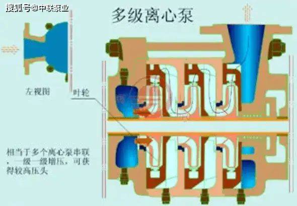
Figure 1 horizontal speculation multi-stage centrifuge pump structure figure
1 pump, 2 pump, 3-axis bearing; 4-axis; 5-leaf; 6-pump; 7-axis head pump
The pumps are snail-shaped pumps, each of which has a snail-like chamber at the outer edge, which is equivalent to a series of single-stage snail pumps mounted on the same axis, and are called snail-type multi-phase pumps. Since the pump is horizontal, both the inhaler and the discharge are placed directly on the pump, which can be easily repaired by removing the pump cover and exposing the entire rotor, which is suspended when the rotor is overhauled, without having to be removed from the pipe. The wheel of the pump is usually set with even-number symmetry, and most of the axle forces are balanced and therefore do not require an axle balancing device. The horizontal stratification multi-stage pump flow range is 450-1500 m'/h with a maximum stretch of 1800 m hz0. As a result of the symmetry of the wheel, there is a cross stream inside the pump shell, as shown in figure 2, it is larger than the size of a phased multi-stage pump with the same performance, complex casting processes, high positioning requirements for the pump cap and pump body, and when pressure is high, it is difficult to seal the combined surface of the pump cap and pump body。
Figure 2 multi-stage centrifuge pumps with a symmetrical line of leaves
2. Structures of multi-stage centrifuge pumps
When pressure is high, multi-stage centrifuge pumps are usually used. The pump is a vertically divided multi-phased pump, consisting of a front, a tail and several medium segments, which are connected to a whole with four long rod bolts. The number of leaf wheels installed on the pump axis represents the number of stages of the centrifuge pump, each of which is equipped with a steering wheel in the medium segment, which functions essentially the same as the snail shell, mainly by converting the kinetic energy into static energy. The wheel is usually single-sniffed and the smokers are in one direction. In order to balance axle direction, a balance disk is installed at the end of the paragraph and connected with the front import with a balancing tube. In the course of its work, the rotor can move around the axis to the right and the left, balancing the axis of the wheel group with the thrust of the balance plate and keeping the rotor close to the balance position. Both ends of the axis are supported by axle bearings and placed on the bearings of the axis, each of which has an axle seal。
Depending on the place of use, a series of multiple stages of centrifuge pumps can be divided into a general series of multiple stages of centrifuge pumps, medium and low pressure boilers for pumps and high pressure boilers for pumps。
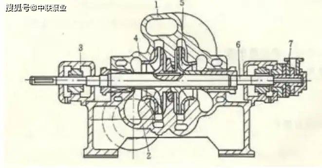
Figure 3 general segmented multi-stage centrifuge pump structure figure
3-litre 4-axis 5-conductor 6-hulling 7-leafhead 8-leaved 9-dash 10-balanced 12-out-water 13-out-water 14-tail 15-axis ethyl 16-axis nut 17-dick 18-balancing plate 19-assembly ethyl component 20-axis 21-axis armour component 22-oil rings 23-axis armor 24-filled pressure cap 25-water seal 26-string bolts
The temperature of liquids delivered to pumps from low-pressure boilers is generally around 110 °c, with essentially the same structure and general sequenced multiple-stage centrifuge pumps, most of which are common to each other. For middle-pressure boilers, the pressure and working temperatures are higher than the pressure, and the requirements for axle sealing units are usually higher, and some bearings are cooled with recycled water, in addition to the need for lubrication. For insulation, some of them are convexed into drum masks outside the pump. Pumps are supported by a centre。
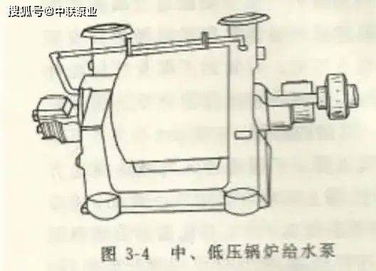
Figure 4 medium and low pressure boilers for pumps
High pressure boilers deliver liquid to pumps at temperatures of 160 - 170°c and export pressure above 15 mpa. Considering the effects of temperature changes, the transition parts of the pumps mostly use alloy materials with the same inflation factor. The wheel was installed on the pump axis and eventually left an axle gap of around 0. 50 mm to prevent the stretching of the pump axis from being damaged during the initial drive due to thermal expansion of the wheel and the crowding between the wheel and the wheel. The support of the pump axis is a central support, so that thermal expansion of the vehicle's post-driving pump is irradiated from the centre of the axis line of the pump, the search of the crew is not damaged and the rotor is in the middle of the pump shell。
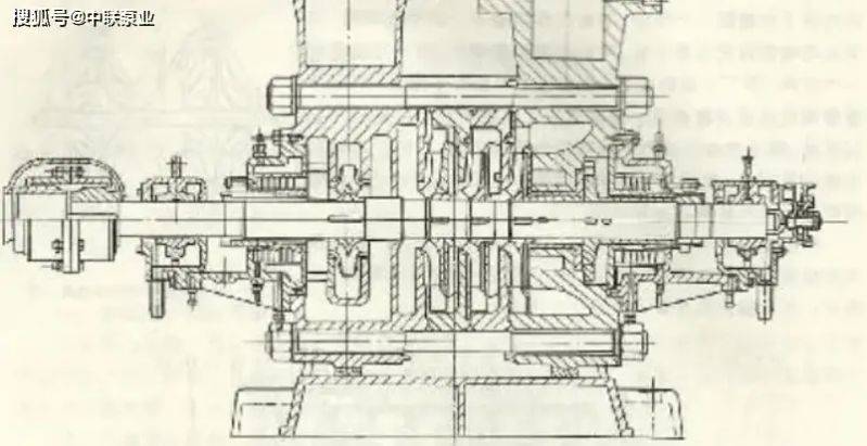
Figure 5 high pressure boilers for pumps
In order to eliminate the co-inspiration effects of the thermal condensation, high-pressure boilers provide vertical and vertical slides to the lower body of the pump, which are compatible with the distribution slots and holes on the pump seat, respectively. The axle bearings of the pump are installed on the front and back of each end, each bearing having three calibrated bolts to regulate the concentricity of the bearings with the pump shell。
The wheel is operating with an axle thrust. There are two measures to balance the thrust of the multi-stage pump: for horizontal symmetry of multi-stager pumps, a positive and reverse installation of the wheel is used to offset each other's thrust. For a multi-stage centrifuge pump, a thrust balancing device is installed at the back end of the upper stage of the wheel to balance the axle thrust generated by the wheel at each stage, as the time wheel is installed in the direction of the axis。
In general, the rotor of a multi-stage segment centrifugal pump moves in axle at a rate of 0. 10 to 0. 15 mm and 10 to 20 times per minute. Therefore, balancing discs and balance rings can be easily worn if the medium in operation contains sand or other solid substances. In order to resist wear and tear, the useful life of the parts is extended and, normally, the balance sheets and balance rings are made of grinding metals, such as copper, grey cast iron, etc。
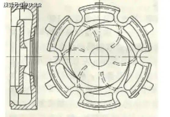
Figure 6
Multistage centrifuge pump operation: a steering wheel is installed outside each of the wheels in the middle of a multi-stage, multi-stage centrifuge pump. The wheel is a fixed, non-moveable disk that functions to convert a portion of the kinetic energy of liquids released from the wheel to static voltage by slowing down and to direct the liquids to the population of the lower leaf. The front of the wheel is a positive directional leaf that surrounds the outer edge of the wheel. The back is a reverse directional leaf that leads the liquid to the population of the lower wheel, the structure of which is shown in figure 6。
After the liquid is thrown out of the wheel, ... The smoothing into the positive directional leaves in the direction of the flow of the liquid continues to flow out along the direction of the directional leaves, the speed of which is gradually decreasing, the static pressure is increasing, and when reaching the cavity on the outermost side of the wheel ... The flow speed is minimal and the static pressure is highest. After the liquid flows from the positive directional leaves, it flows along the axis through the inner spacing sheet of the steering wheel, then internally along the inverse directional leaves, while lowering the circular flow speed, and along the axis into the lower stage。
Compared to snail shells, the outer size of the conductor is smaller and the efficiency of converting kinetic energy into static energy is also lower. Because there are multiple blades in the wheel, when the actual work of the pump deviates from that of the design, the flow of liquids from the wheel is not shaped in a manner consistent with the shape of the wheel, resulting in a greater impact loss and a reduction in efficiency, the centrifuge pump is used in the conductor, the area of efficient work is narrower and the length and efficiency curve is steeper than the snail pump. However, due to the central symmetry of the steering wheel, which does not produce a rudder pressure on the rotor like a snail, multi-stage pumps typically use snails in two segments of the end of the head, while in several parts of the centre。
Because of the complexity of the geometry of the wheel, it is generally made of cast iron。
As with single-stage centrifugal pumps, multiple-stage centrifugal pumps are not self-suctionable and must be pumped before they are activated. Various multi-stage centrifugal pumps work on the principle of high-speed rotation of liquids driven by a leaf wheel, which produces centrifugal power and gives them energy. As a result, liquids in the person's room on the front side of a leaf wheel enter the first stage of the wheel, which is used by the wheel, then enters the first stage of the wheel, which is converted through the first stage of the wheel, then enters the second stage of the wheel, continues the second stage of the wheel and then enters the second stage of the wheel, so on, until they are dumped from the last part of the wheel and collected through the snail shell, before being released from the exit。